Subaru Legacy (2005 year). Service manual — part 961
IDI-9
INSTRUMENTATION/DRIVER INFO
Combination Meter System
3
CHECK FUEL SUB LEVEL SENSOR.
1) Remove the fuel sub level sensor. <Ref. to
FU(H4SO 2.0)-50, REMOVAL, Fuel Sub Level
Sensor.> <Ref. to FU(H4SO 2.5)-53,
REMOVAL, Fuel Sub Level Sensor.> <Ref. to
FU(H4DOTC)-51, REMOVAL, Fuel Sub Level
Sensor.> <Ref. to FU(H6DO)-51, REMOVAL,
Fuel Sub Level Sensor.>
2) Measure the resistance between fuel sub
level sensor terminals when the float is in
FULL or EMPTY position.
Terminals
No. 1 — No. 2:
Is the resistance 1.0 — 3.0
Ω
(FULL) or 61 — 63
Ω
(EMPTY)?
Replace the fuel
sub level sensor.
4
CHECK HARNESS BETWEEN FUEL SUB-
LEVEL SENSOR AND BODY INTEGRATED
MODULE.
1) Disconnect the connector from body inte-
grated module.
2) Measure the resistance between fuel sub
level sensor harness connector terminal and
body integrated module harness connector ter-
minal.
Connector & terminal
(R59) No. 1 — (B281) No. 19:
Is the resistance less than 10
Ω?
Repair the wiring
harness.
5
CHECK HARNESS BETWEEN FUEL LEVEL
SENSOR AND FUEL SUB LEVEL SENSOR.
Measure the resistance between fuel level sen-
sor harness connector terminal and fuel sub
level sensor harness connector terminal.
Connector & terminal
(R58) No. 1 — (R59) No. 2:
Is the resistance less than 10
Ω?
Repair the wiring
harness.
6
CHECK FUEL LEVEL SENSOR GROUND
CIRCUIT.
Measure the resistance between fuel level sen-
sor harness connector terminal and chassis
ground.
Connector & terminal
(R58) No. 4 — Chassis ground:
Is the resistance less than 10
Ω?
Replace the meter
case assembly.
Repair the wiring
harness.
Step
Check
Yes
No
IDI-10
Vehicle-id:
SIE-id:S907607a10:B:INSPECTION
∼
INSTRUMENTATION/DRIVER INFO
Combination Meter System
8. CHECK ENGINE COOLANT TEMPERATURE SENSOR.
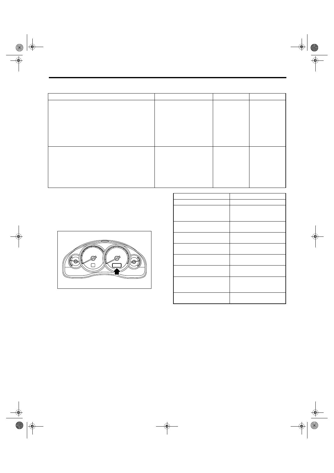
9. COMMUNICATION ERROR DISPLAY
When the following error code is displayed in the
odo/trip meter, inspect the communication circuit
since the communication malfunction is generated
between each control module. <Ref. to LAN(diag)-
2, Basic Diagnostic Procedure.>
Step
Check
Yes
No
1
CHECK COMMUNICATION ERROR DIS-
PLAY.
1) Set the ignition switch to ON.
2) Check that the error code is displayed in
odo/trip meter.
Is the error code “Er xx” dis-
played in odo/trip meter?
Check the commu-
nication circuit.
<Ref. to IDI-10,
COMMUNICA-
TION ERROR
DISPLAY,
INSPECTION,
Combination
Meter System.>
2
CHECK ENGINE COOLANT TEMPERATURE
SENSOR.
Check the engine coolant temperature sensor.
<Ref. to EN(H4SO 2.0)(diag)-2, Basic Diag-
nostic Procedure.> <Ref. to
EN(H4DOTC)(diag)-2, Basic Diagnostic Proce-
dure.> <Ref. to EN(H6DO)(diag)-2, Basic
Diagnostic Procedure.>
Is the engine coolant tempera-
ture sensor OK?
Replace the meter
case assembly.
Replace the
engine coolant
temperature sen-
sor.
IDI00100
Error code
Remarks
Er IU
Malfunction in integrated unit
Er
−−
Simultaneous malfunction of
high/low speed CAN com-
munication
Er HC
Malfunction of high-speed
CAN communication
Er LC
Malfunction of low-speed
CAN communication
Er EG
EGI Communication mal-
function
Er TC
TCM Communication mal-
function
Er Ab
ABSCM/VDCCM Communi-
cation malfunction
Er SP
ABSCM/VDCCM DTC infor-
mation, vehicle speed pulse
malfunction
Er SS
Wheel speed data malfunc-
tion
IDI-11
INSTRUMENTATION/DRIVER INFO
Combination Meter System
10.DTC DISPLAY MODE
When DTC display mode is operated, {ECM}, {TCM}, {ABSCM/VDCCM} is displayed repeatedly in this order
by pressing the odo/trip meter button. DTC is displayed in the following table according to type of control
module, receiving DTC, DTC detected, No DTC. If CAN communication is broken down, “-----” is displayed.
Control module
Condition
Display
ECM
Receiving DTC
Trip “A” + “P (blinking)”
DTC detected
Trip “A” + “Pxxxx”
No DTC
Trip “A” + “P----”
TCM
Receiving DTC
Trip “B” + “P (blinking)”
DTC detected
Trip “B” + “Pxxxx”
No DTC
Trip “B” + “P----”
ABSCM/VDCCM
Receiving DTC
Trip “A” + “C (blinking)”
DTC detected
Trip “A” + “Cxxxx”
No DTC
Trip “A” + “C----”
When CAN communication is
broken down.
—
“-----”
IDI-12
Vehicle-id:
SIE-id:S907843a21:B:INSPECTION
∼
INSTRUMENTATION/DRIVER INFO
Clock System
3. Clock System
A: WIRING DIAGRAM
1. CLOCK
<Ref. to WI-311, WIRING DIAGRAM, Clock System.>
B: INSPECTION
1. SYMPTOM CHART
Symptom
Repair order
Reference
No display is shown.
(1) Power supply
(2) Clock body
<Ref. to IDI-13, CHECK
POWER SUPPLY AND
GROUND CIRCUIT,
INSPECTION, Clock
System.>
Illumination does not illuminate.
(1) Illumination power supply
(2) Clock body
<Ref. to IDI-13, CHECK
ILLUMINATION CIR-
CUIT, INSPECTION,
Clock System.>
Brightness does not change even when bright
switch is pressed.
(1) Bright switch
(2) Clock body
<Ref. to IDI-13, CHECK
BRIGHT CIRCUIT,
INSPECTION, Clock
System.>
“Acc” or “ign” is displayed.
ACC or ignition power supply
<Ref. to IDI-14, CHECK
ACC OR IGNITION
POWER SUPPLY,
INSPECTION, Clock
System.>
“Err” is displayed in all items.
(1) Communication circuit between combination
meter and clock
(2) Clock body
<Ref. to IDI-14, CHECK
COMMUNICATION
CIRCUIT, INSPEC-
TION, Clock System.>
“Err” is displayed when a specified item is
selected.
Communication circuit between combination
meter and each control module
<Ref. to IDI-10, COM-
MUNICATION ERROR
DISPLAY, INSPEC-
TION, Combination
Meter System.>
Нет комментариевНе стесняйтесь поделиться с нами вашим ценным мнением.
Текст