Subaru Legacy (2005 year). Service manual — part 959
INSTRUMENTATION/DRIVER INFO
IDI
Page
General Description . . . . . . . . . . . . . . . . . . . . . 2
Combination Meter System. . . . . . . . . . . . . . . . . . .3
Clock System . . . . . . . . . . . . . . . . . . . . . . . 12
Combination Meter. . . . . . . . . . . . . . . . . . . . . 15
Speedometer. . . . . . . . . . . . . . . . . . . . . . . .17
Tachometer . . . . . . . . . . . . . . . . . . . . . . . ...18
Fuel Gauge . . . . . . . . . . . . . . . . . . . . . . . ...19
Engine Coolant Temperature Gauge . . . . . . . . . . . . . . 20
Clock . . . . . . . . . . . . . . . . . . . . . . . . . . .21
IDI-2
Vehicle-id:
SIE-id:S907001a22:A:SPECIFICATION
∼
INSTRUMENTATION/DRIVER INFO
General Description
1. General Description
A: SPECIFICATION
B: CAUTION
• Be careful not to damage the meters and instrument panel.
• Be careful not to damage the meter glass.
• Make sure the electrical connector is connected securely.
• After installation, make sure that each meter operates normally.
• Use gloves to avoid damage and getting fingerprints on the glass surface and meter surfaces.
• Do not apply an excessive force on the printed circuit.
• Do not drop or otherwise apply impact.
• When the combination meter of model with immobilizer has been replaced, be sure to perform the regis-
tration procedure of immobilizer.
C: PREPARATION TOOL
1. GENERAL TOOL
Combination meter
Speedometer
Stepping motor type
Tachometer
Engine coolant temperature gauge
Fuel gauge
Malfunction indicator light
LED
Oil pressure warning light
ABS warning light
Airbag warning light
Seat belt warning light
Door open warning light
Brake fluid and parking brake warning light
Low fuel warning light
Charge indicatior light
ATF temperature warning light
AWD warning light
Vehicle dynamics control (VDC) warning light
Vehicle dynamics control (VDC) indicator light
Turn signal indicator light
HI-beam indicator light
Immobilizer indicator light
Cruise indicator light
Cruise set indicator light
Front fog light indicator light
Rear fog light indicator light
AWD LO indicator light
SPORT indicator light
AT select lever position indicator light
Light illumination indicator light
Meter illumination light
LCD back light
Odo/Trip indicator
LCD
SPORT shift indicator
TOOL NAME
REMARKS
Circuit tester
Used for measuring resistance and voltage.
IDI-3
INSTRUMENTATION/DRIVER INFO
Combination Meter System
2. Combination Meter System
A: WIRING DIAGRAM
1. COMBINATION METER
<Ref. to WI-307, WIRING DIAGRAM, Combination
Meter System.>
B: INSPECTION
1. SELF-DIAGNOSIS
The self-diagnosis (checking of each meter, warn-
ing light, indicator, illumination, LCD, buzzer
sound) of combination meter can be performed in
the following procedure.
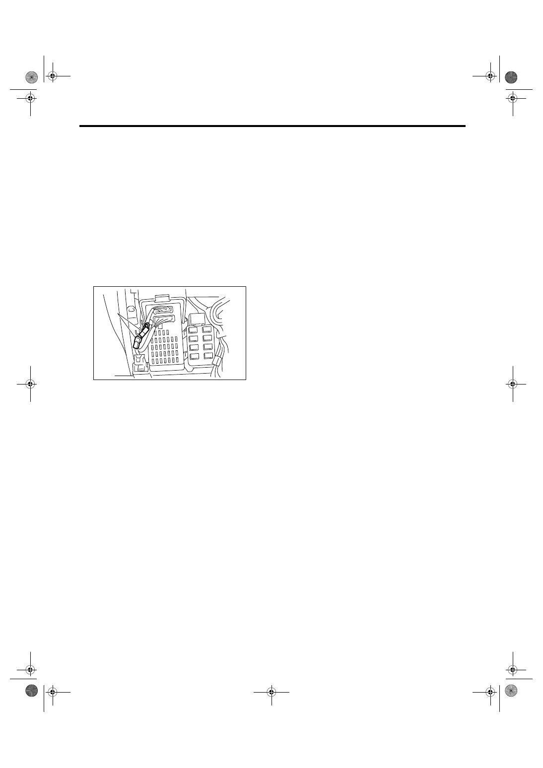
1) Connect the diagnostic connector (A) near the
fuse & relay box.
2) Turn the ignition switch to ON.
3) While meter indicator needle deflecting, press
the odo/trip meter knob twice.
NOTE:
When odo/trip meter knob is pressed only once,
display mode is shifted to DTC display mode. <Ref.
to IDI-11, DTC DISPLAY MODE, INSPECTION,
Combination Meter System.>
When the self-diagnosis function is operated, the
checking of warning light, indicator, and LCD dis-
play is performed, hereafter, every pressing the
odo/trip meter knob, the operation check is per-
formed in the order of meter, illumination and buzz-
er. <Ref. to IDI-4, LIST OF SELF-DIAGNOSIS
MODE OPERATION, INSPECTION, Combination
Meter System.> To cancel the self-diagnosis
mode, set the ignition switch to OFF or disconnect
the diagnosis connector.
NOTE:
When the engine starts during diagnosis, the self-
diagnosis mode is not cancelled, however, once
the vehicle starts driving, the self-diagnosis mode
is cancelled automatically for safety.
(A)
IDI00133
IDI-4
Vehicle-id:
SIE-id:S907607a10:B:INSPECTION
∼
INSTRUMENTATION/DRIVER INFO
Combination Meter System
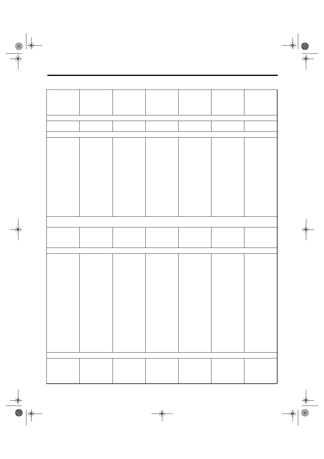
2. LIST OF SELF-DIAGNOSIS MODE OPERATION
Speedometer,
tachometer, fuel
gauge, engine
coolant temper-
ature gauge
Microcomputer
running type
warning light,
indicator light
AT select lever
position indica-
tor light
Odo/Trip indica-
tor
SPORT shift
indicator
Illumination
(indicator nee-
dle, plate, ring,
LCD)
Buzzer (SPORT
shift buzzer,
speed warning
buzzer)
Step 0. Processing to self-diagnosis mode
Operating initial
operation
Initial illuminat-
ing
Normal
Normal
Initial illuminat-
ing
Initial illuminat-
ing
Not beep.
Step 1-1. Check each indication after initial operation
Repeat the
sweep opera-
tion (After hold-
ing on lowest
position for one
second, reaches
to highest posi-
tion within 5
seconds, and
after holding on
highest position
for one second,
reaches to low-
est position
within 5 sec-
onds).
Light ON
With the high-
est brightness,
illuminate the
position sequen-
tially at a cycle
of 1.5 seconds.
Perform the seg-
ment check. For
the illumination
order, refer to
the illumination
order table.
Perform the seg-
ment check. For
the illumination
order, refer to
the illumination
order table.
Light at the
highest bright-
ness.
Not beep.
Step 1-2. Press the trip knob (trip knob input is not accepted till the meter indicator needle reaches the highest position): sweep
complete, AT select lever position indicator display is set
After complet-
ing sweep in
step 1-1, back to
lowest position.
Light ON
Keep the posi-
tion indicated
when the trip
knob is pressed.
Underbar “ _ ” is
displayed.
“1” is displayed.
Light at the
highest bright-
ness.
Not beep.
Step 2-1. Press the trip knob, and hold it: Check each meter
All meters are
moved simulta-
neously in every
0.5 sec. from
the lowest posi-
tion to highest
position.
Speedometer/
Tachometer:
Approx. 5
degrees at
every move-
ment.
Engine coolant
temperature
gauge/Fuel
gauge: Approx.
2 degrees at
every move-
ment.
Light OFF
Keep the posi-
tion indicated
that set in step
1-2.
Display the cur-
rent meter
directing angle
on odometer.
Ex.) Display
“135054” when
Speedometer/
Tachometer:
135 degree,
Engine coolant
temperature
gauge/Fuel
gauge: 54
degree.
“
▼2” is dis-
played.
Light at the
highest bright-
ness.
Not beep.
Step 2-2. Release the trip knob: Specifying the meter directing position
Stop at direct-
ing position
when the trip
knob is
released.
Light OFF
Keep the posi-
tion indicated
that specified at
step 1-2.
Display the cur-
rent meter
directing angle
on odometer.
“2” is displayed.
Light at the
highest bright-
ness.
Not beep.
Нет комментариевНе стесняйтесь поделиться с нами вашим ценным мнением.
Текст