Subaru Legacy (2005 year). Service manual — part 533
4AT-113
AUTOMATIC TRANSMISSION
Drive Pinion Shaft Assembly
Corrective action: Increase thickness of drive pin-
ion height adjusting shim in order to bring drive pin-
ion close to hypoid driven gear.
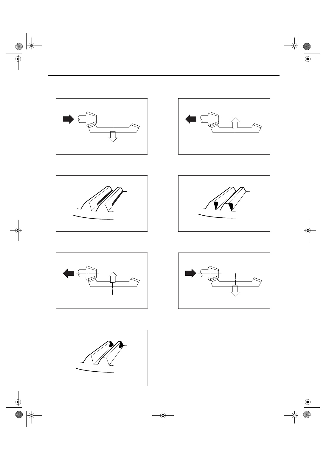
• Flank contact
Checking item: Backlash is too small.
Contact pattern
Corrective action: Reduce thickness of drive pinion
height adjusting shim in order to bring drive pinion
away from hypoid driven gear.
• Toe contact (inside end contact)
Checking item: Contact area is too small.
Contact pattern
Corrective action: Reduce thickness of drive pinion
height adjusting shim in order to bring drive pinion
away from hypoid driven gear.
• Heel contact (outside end contact)
Checking item: Contact area is too small.
Contact pattern
Corrective action: Increase thickness of drive pin-
ion height adjusting shim in order to bring drive pin-
ion close to hypoid driven gear.
AT-00212
AT-00209
AT-00213
AT-00210
AT-00213
AT-00211
AT-00212
4AT-114
AUTOMATIC TRANSMISSION
Drive Pinion Shaft Assembly
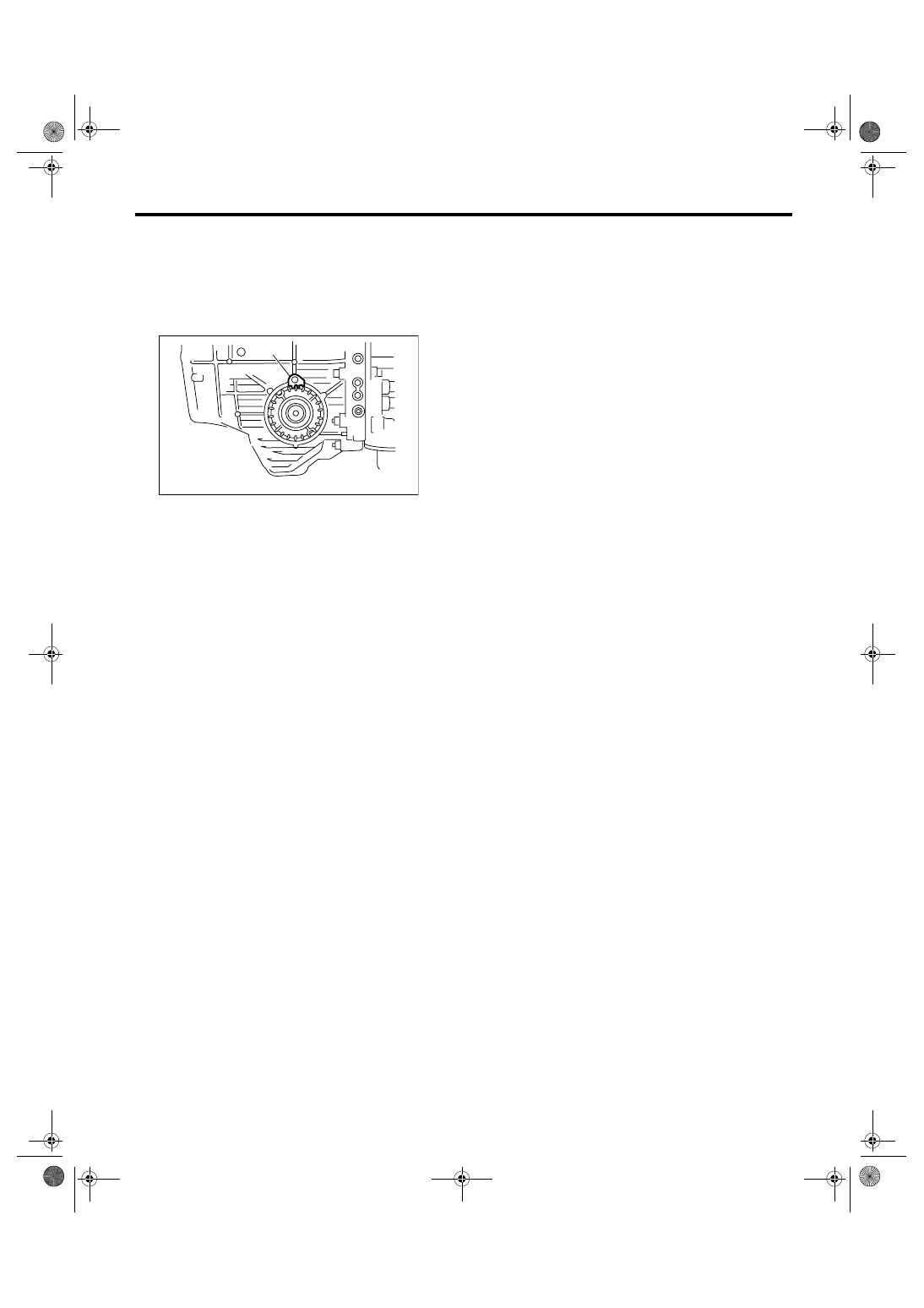
6) If tooth contact is correct, mark the retainer posi-
tion and loosen it. After fitting a new O-ring and oil
seal, screw in the retainer to the marked position.
Tighten the lock plate with the specified torque.
Tightening torque:
25 N
⋅
m (2.5 kgf-m, 18.4 ft-lb)
(A) Lock plate
AT-00214
(A)
4AT-115
AUTOMATIC TRANSMISSION
Front Differential Assembly
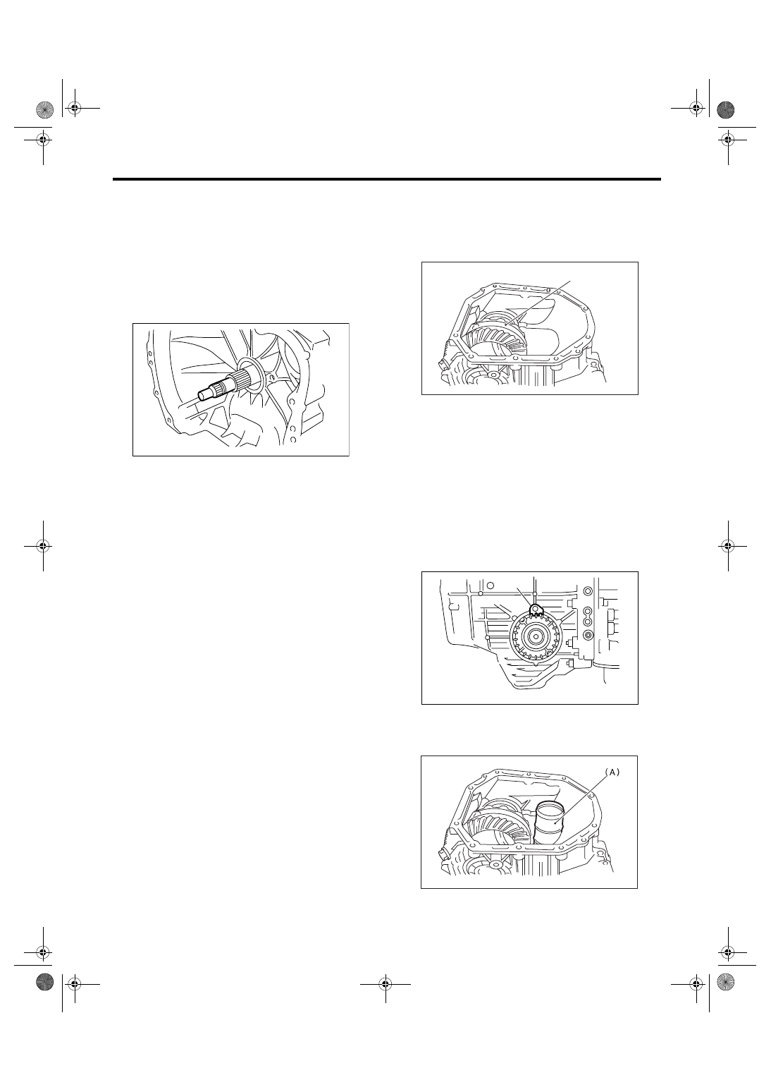
40.Front Differential Assembly
A: REMOVAL
1) Remove the transmission assembly from vehi-
cle. <Ref. to 4AT-39, REMOVAL, Automatic Trans-
mission Assembly.>
2) Pull out the torque converter clutch assembly.
<Ref. to 4AT-81, REMOVAL, Torque Converter
Clutch Assembly.>
3) Remove the input shaft.
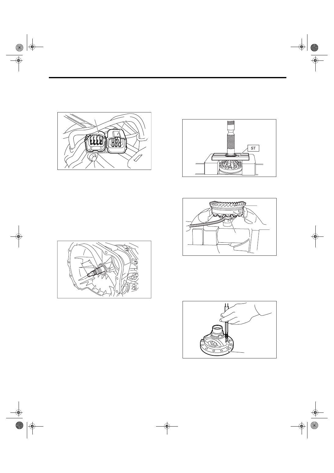
4) Lift up the lever on rear part of transmission har-
ness connector, and then remove it from stay.
5) Remove the inhibitor switch from stay.
6) Remove the oil charge pipe. <Ref. to 4AT-80,
REMOVAL, Oil Charge Pipe.>
7) Remove the oil cooler inlet and outlet pipes.
<Ref. to 4AT-68, REMOVAL, ATF Cooler Pipe and
Hose.>
8) Separate the converter case and transmission
case. <Ref. to 4AT-102, REMOVAL, Converter
Case.>
9) Remove the seal pipe.
10) Remove the differential side retainers using
ST.
NOTE:
Hold the differential case assembly by hand to
avoid damaging the retainer mounting hole of con-
verter case.
ST
499787000
WRENCH ASSY
11) Remove the differential assembly without dam-
aging the installation part of retainer.
B: INSTALLATION
1) When installing the differential assembly to
case, be careful not to damage the inside of case
(particularly, the differential side retainer mating
surface).
2) Install the O-ring to left and right side retainer.
3) Install the side retainers using ST. <Ref. to 4AT-
119, ADJUSTMENT, Front Differential Assembly.>
ST
499787000
WRENCH ASSY
4) Adjust the front differential backlash. <Ref. to
4AT-119, ADJUSTMENT, Front Differential As-
sembly.>
5) Install the lock plate.
Tightening torque:
25 N
⋅
m (2.5 kgf-m, 18.4 ft-lb)
6) Install new seal pipe to converter case.
AT-00114
(A) Differential ASSY
(A) Lock plate
(A) Seal pipe
AT-00215
(A)
AT-00214
(A)
AT-00176
4AT-116
AUTOMATIC TRANSMISSION
Front Differential Assembly
7) Install the converter case to transmission case.
<Ref. to 4AT-102, INSTALLATION, Converter
Case.>
8) Insert the inhibitor switch and transmission con-
nector to stay.
9) Install the oil cooler pipe. <Ref. to 4AT-70, IN-
STALLATION, ATF Cooler Pipe and Hose.>
10) Install the oil charge pipe with a O-ring. <Ref. to
4AT-80, INSTALLATION, Oil Charge Pipe.>
11) Insert the input shaft while rotating it lightly by
hand, and then check the protrusion amount.
Normal protrusion A:
50 — 55 mm (1.97 — 2.17 in)
12) Install the torque converter clutch assembly.
<Ref. to 4AT-81, INSTALLATION, Torque Convert-
er Clutch Assembly.>
13) Install the transmission assembly into vehicle.
<Ref. to 4AT-42, INSTALLATION, Automatic
Transmission Assembly.>
C: DISASSEMBLY
1. DIFFERENTIAL CASE ASSEMBLY
1) Remove the taper roller bearing using ST and
press.
ST
498077000
REMOVER
2) Secure the case in a vise, remove the hypoid
driven gear tightening bolts, and then separate the
hypoid driven gear into case (RH) and case (LH).
3) Pull out the straight pin and shaft, and then re-
move the differential bevel gear, washer and differ-
ential bevel pinion.
(A) Transmission connector
(B) Inhibitor switch connector
AT-01351
(B)
(A)
AT-03204
A
(A) Hypoid driven gear
(B) Differential case (RH)
(C) Differential case (LH)
(A) Differential case (RH)
AT-00216
(B)
AT-00217
(A)
(C)
AT-00218
(A)
Нет комментариевНе стесняйтесь поделиться с нами вашим ценным мнением.
Текст