Subaru Legacy (2005 year). Service manual — part 532
4AT-109
AUTOMATIC TRANSMISSION
Drive Pinion Shaft Assembly
39.Drive Pinion Shaft Assembly
A: REMOVAL
1) Remove the transmission assembly from vehi-
cle. <Ref. to 4AT-39, REMOVAL, Automatic Trans-
mission Assembly.>
2) Pull out the torque converter clutch assembly.
<Ref. to 4AT-81, REMOVAL, Torque Converter
Clutch Assembly.>
3) Remove the input shaft.
4) Lift up the lever on rear side of transmission har-
ness connector, and then disconnect it from the
stay.
5) Disconnect the inhibitor switch connector from
stay.
6) Disconnect the air breather hose. <Ref. to 4AT-
79, REMOVAL, Air Breather Hose.>
7) Remove the oil charge pipe. <Ref. to 4AT-80,
REMOVAL, Oil Charge Pipe.>
8) Remove the oil cooler inlet and outlet pipes.
<Ref. to 4AT-68, REMOVAL, ATF Cooler Pipe and
Hose.>
9) Separate the converter case and transmission
case part. <Ref. to 4AT-102, REMOVAL, Converter
Case.>
10) Separate the transmission case and extension
case part. <Ref. to 4AT-83, REMOVAL, Extension
Case.>
11) Remove the reduction drive gear. (MP-T mod-
el) <Ref. to 4AT-97, REMOVAL, Reduction Drive
Gear.>
12) Remove the center differential carrier. (VTD
model) <Ref. to 4AT-99, REMOVAL, Center Differ-
ential Carrier.>
13) Remove the reduction driven gear. <Ref. to
4AT-95, REMOVAL, Reduction Driven Gear.>
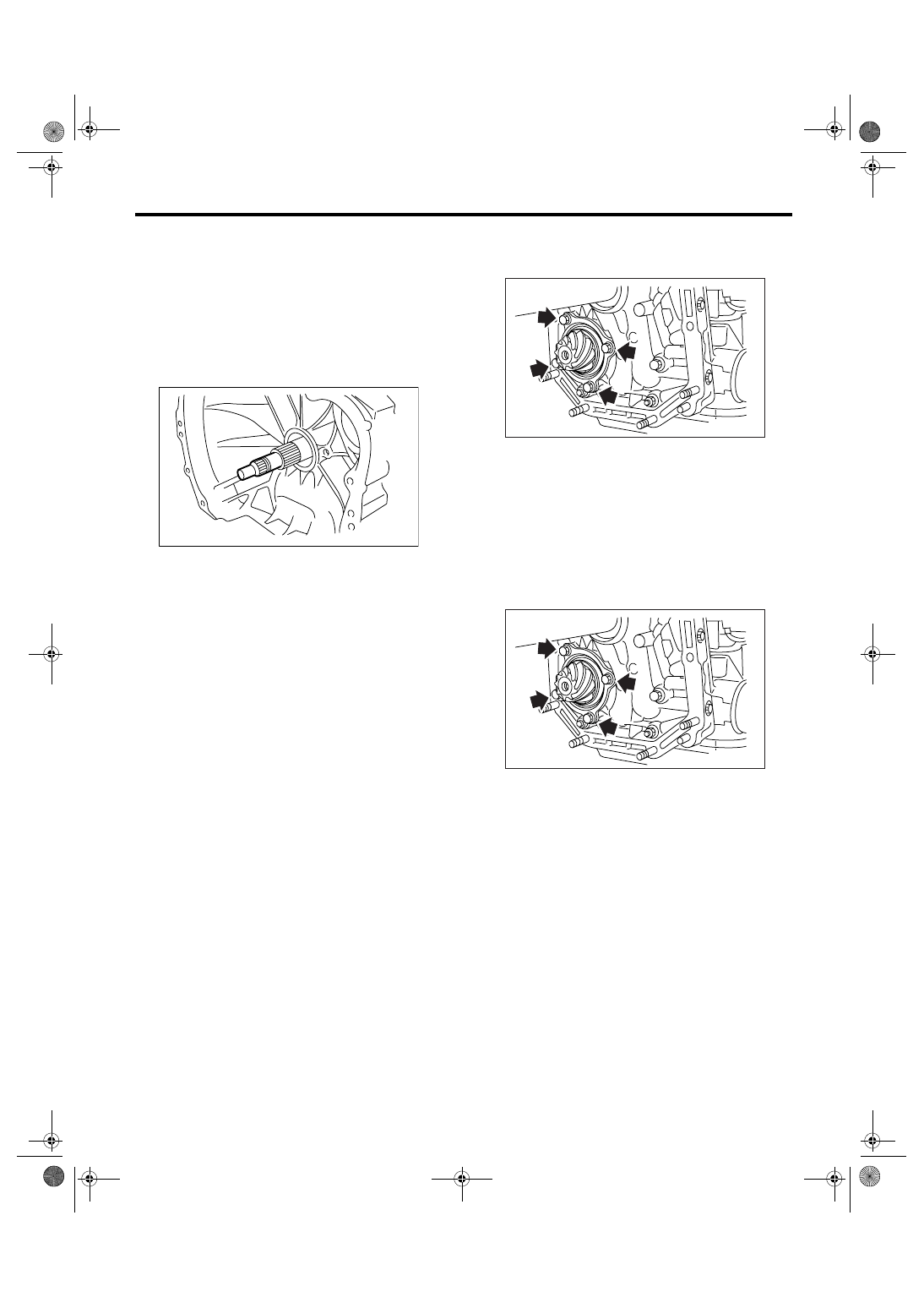
14) Remove the drive pinion shaft mounting bolt
and remove the drive pinion shaft assembly from oil
pump housing.
B: INSTALLATION
1) Assemble the drive pinion assembly to oil pump
housing.
NOTE:
• Be careful not to bend the shim.
• Be careful not to press-fit the pinion into housing
bore.
Tightening torque:
40 N
⋅
m (4.1 kgf-m, 29.5 ft-lb)
2) Combine the torque converter case with trans-
mission case. <Ref. to 4AT-102, INSTALLATION,
Converter Case.>
3) Install the reduction driven gear. <Ref. to 4AT-
95, INSTALLATION, Reduction Driven Gear.>
4) Install the reduction drive gear. (MP-T model)
<Ref. to 4AT-97, INSTALLATION, Reduction Drive
Gear.>
5) Install the center differential carrier. (VTD model)
<Ref. to 4AT-99, INSTALLATION, Center Differen-
tial Carrier.>
6) Combine the transmission case with extension
case, and then install the rear vehicle speed sen-
sor. <Ref. to 4AT-83, INSTALLATION, Extension
Case.>
7) Insert the inhibitor switch and transmission con-
nector to stay.
8) Install the oil cooler inlet and outlet pipes. <Ref.
to 4AT-70, INSTALLATION, ATF Cooler Pipe and
Hose.>
9) Install the oil charge pipe with O-ring.
AT-00114
AT-01252
AT-01252
4AT-110
AUTOMATIC TRANSMISSION
Drive Pinion Shaft Assembly
10) Insert the input shaft while rotating it lightly by
hand, and then check the protrusion amount.
Normal protrusion A:
50 — 55 mm (1.97 — 2.17 in)
11) Install the torque converter clutch assembly.
<Ref. to 4AT-81, INSTALLATION, Torque Convert-
er Clutch Assembly.>
12) Install the transmission assembly into vehicle.
<Ref. to 4AT-42, INSTALLATION, Automatic
Transmission Assembly.>
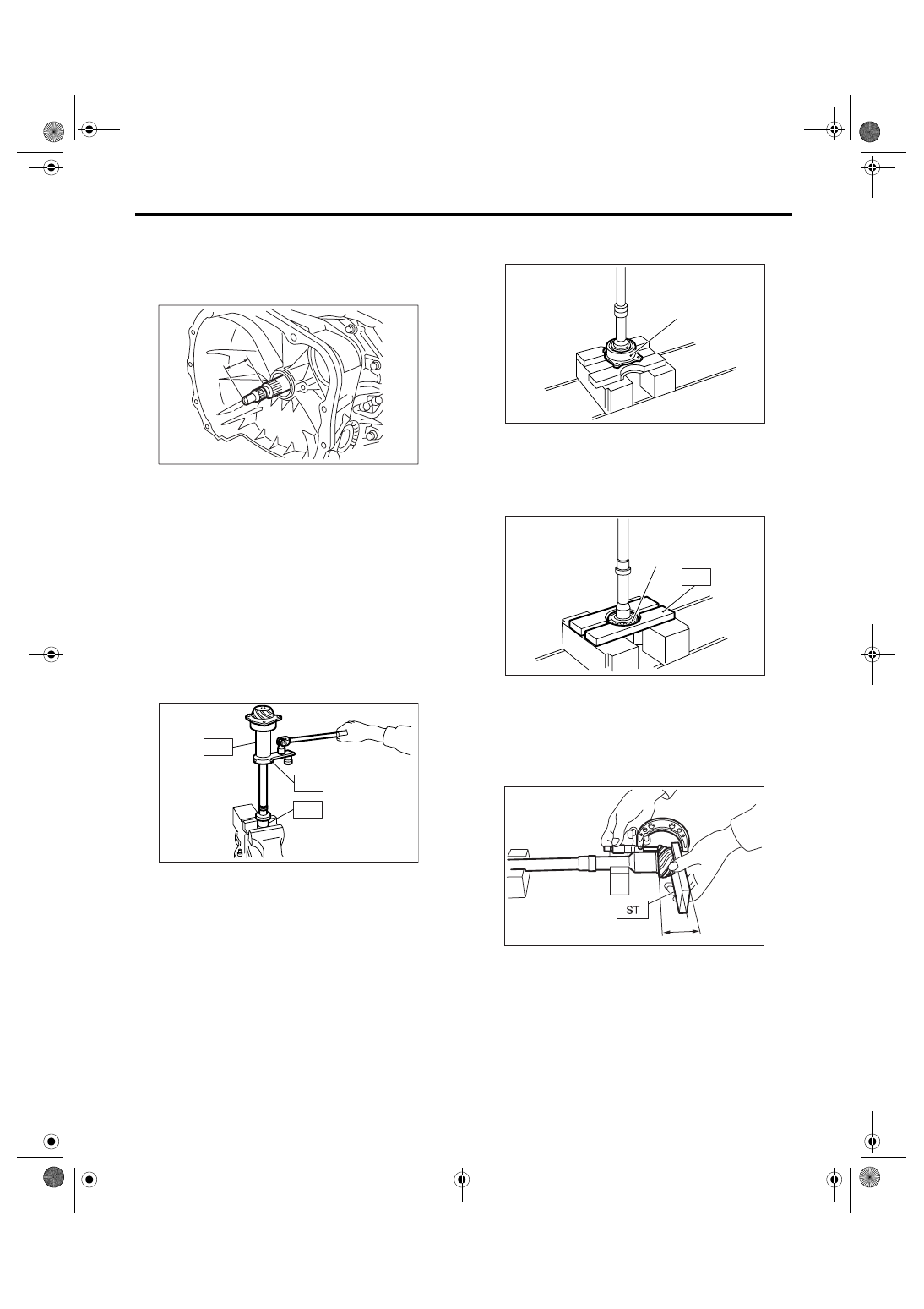
C: DISASSEMBLY
1) Remove the caulking part of lock nut, and then
remove the lock nut with holding rear spline part of
shaft using ST1 and ST2. Pull out the drive pinion
collar.
ST1
498937110
HOLDER
ST2
499787700
WRENCH
ST3
499787500
ADAPTER
2) Remove the O-ring.
3) Separate the roller bearing and outer race from
shaft using press.
4) Separate the front roller bearing from shaft using
press and ST.
ST
498517000
REPLACER
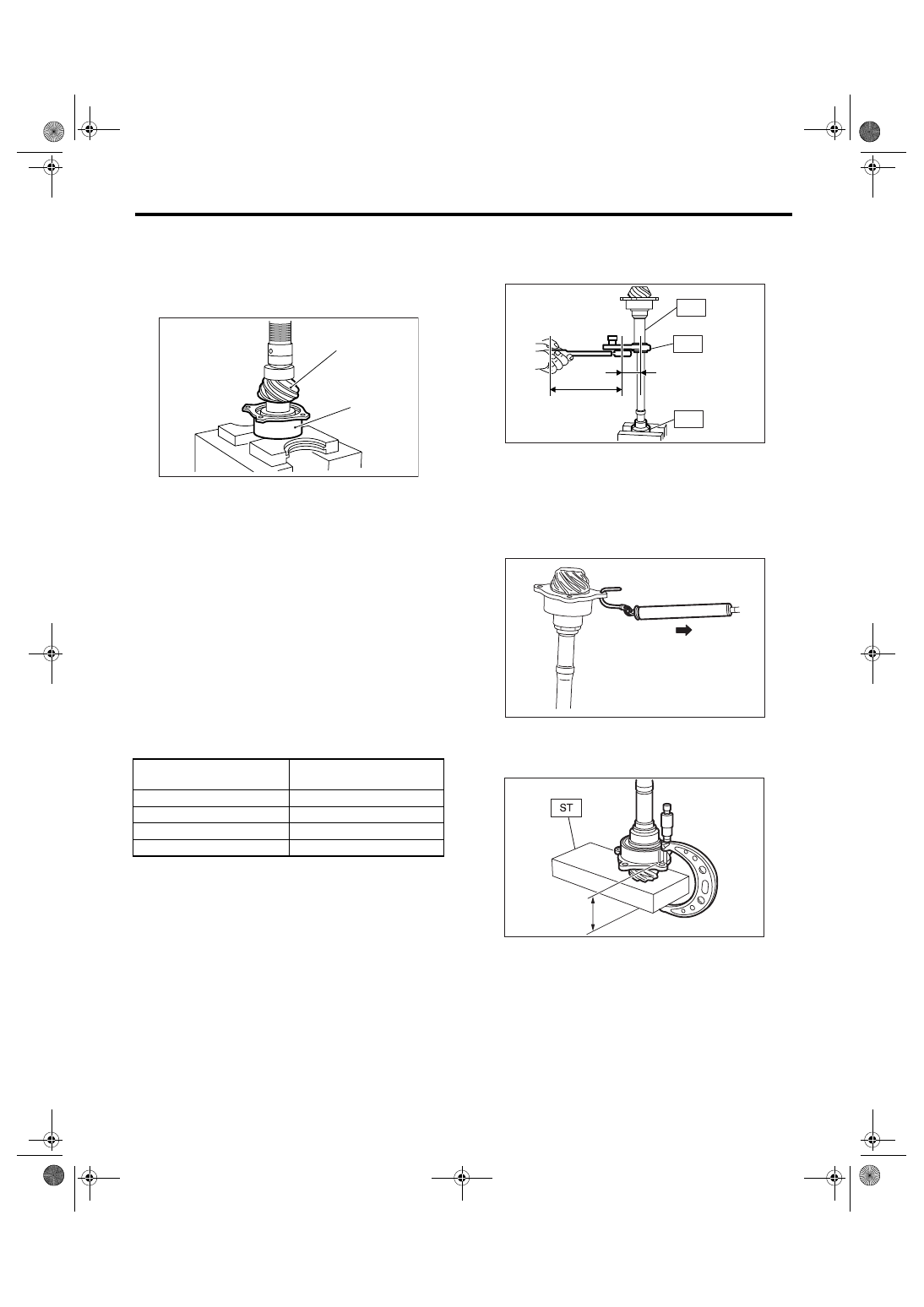
D: ASSEMBLY
1) Measure the dimension “A” of drive pinion shaft
using ST.
ST
398643600
GAUGE
AT-03204
A
AT-00197
ST1
ST3
ST2
(A) Outer race
(A) Front roller bearing
AT-00198
(A)
AT-00199
(A)
ST
A
AT-00200
4AT-111
AUTOMATIC TRANSMISSION
Drive Pinion Shaft Assembly
2) Using a press, press-fit the new roller bearing
into specified position.
NOTE:
If excessive force is applied to roller bearing, the
roller bearing will not turn easily.
3) After applying ATF to a new O-ring and fitting it
to the shaft, attach the drive pinion collar to shaft.
4) Install the lock washer to drive pinion shaft in
proper direction.
5) Tighten new lock nuts using ST1, ST2 and ST3.
Calculate the lock washer and lock nut specifica-
tion using following formula.
T2 = L2/(L1 + L2)
× T1
T1: 116 N
⋅m (11.8 kgf-m, 85.3 ft-lb)
[Required torque setting]
T2: Tightening torque
L1: ST2 length 0.072 m (2.83 in)
L2: Torque wrench length
Example:
ST1
498937110
HOLDER
ST2
499787700
WRENCH
ST3
499787500
ADAPTER
NOTE:
Install the ST2 to torque wrench as straight as pos-
sible.
6) Measure the starting torque of bearing. Make
sure the starting torque is within the specification. If
the torque is not within specification, replace the
roller bearing.
Starting torque:
7.6 — 38.1 N (0.776 — 3.88 kgf, 1.7 — 8.6 lbf)
7) Stake the caulking of lock nut at two points.
8) Measure the dimension “B” of drive pinion shaft
ST
398643600
GAUGE
9) Calculate the thickness “t” (mm) of drive pinion
shim.
t = 6.5
± 0.0625 − (B − A)
(A) Drive pinion shaft
(B) Roller bearing
Torque wrench length
m (in)
Tightening torque
N
⋅m (kgf-m, ft-lb)
0.4 (15.75)
98 (10.0, 72)
0.45 (17.72)
100 (10.2, 73.8)
0.5 (19.69)
101 (10.3, 74.5)
0.55 (21.65)
102 (10.4, 75)
AT-00201
(B)
(A)
ST1
AT-00202
L1 [m (in)]
L2 [m (in)]
ST2
ST3
AT-00203
B
AT-00204
4AT-112
AUTOMATIC TRANSMISSION
Drive Pinion Shaft Assembly
10) Select three or less shims from following table.
E: INSPECTION
• Make sure that all component parts are free of
scratches, holes and other faults.
• Adjust the teeth alignment. <Ref. to 4AT-112,
ADJUSTMENT, Drive Pinion Shaft Assembly.>
F: ADJUSTMENT
1) Remove the liquid gasket from the mating sur-
face completely.
2) Install the oil pump housing assembly to convert-
er case, and secure them with tightening four bolts
evenly.
NOTE:
Use an old gasket or aluminum washer so as not to
damage the mating surface of housing.
Tightening torque:
41 N
⋅
m (4.2 kgf-m, 30.4 ft-lb)
3) Rotate the drive pinion several times using ST1
and ST2.
ST1
498937110
HOLDER
ST2
499787700
WRENCH
4) Adjust backlash between drive pinion and driven
gear. <Ref. to 4AT-119, ADJUSTMENT, Front Dif-
ferential Assembly.>
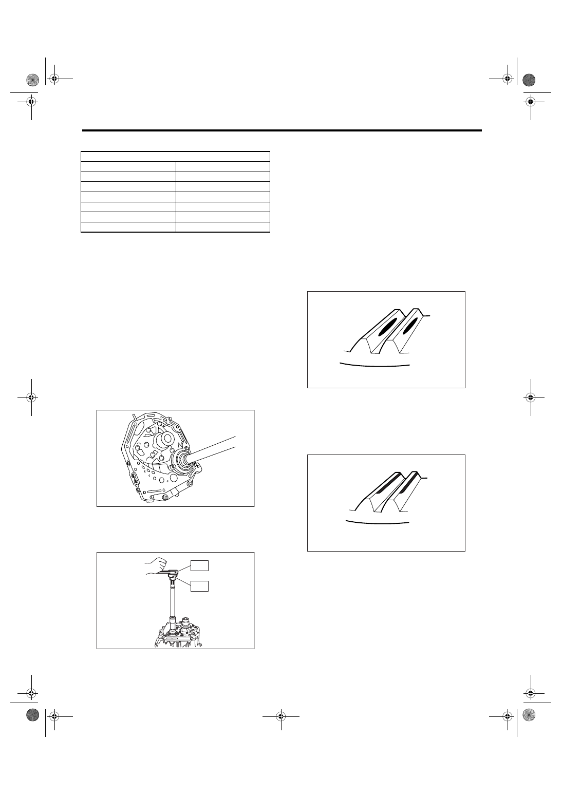
5) Apply red lead evenly to the surfaces of three or
four teeth on driven gear. Rotate the drive pinion in
the forward and reverse directions for several
times. Remove the oil pump housing, and check
the tooth contact pattern.
If the tooth contact is improper, readjust the back-
lash or shim thickness. <Ref. to 4AT-119, AD-
JUSTMENT, Front Differential Assembly.>
• Correct tooth contact
Checking item: Tooth contact pattern is slightly
shifted toward to toe side under no-load
rotation. (When loaded, it moves toward heel
side.)
• Face contact
Checking item: Backlash is too large.
Contact pattern
Drive pinion shim
Part No.
Thickness mm (in)
31451AA050
0.150 (0.0059)
31451AA060
0.175 (0.0069)
31451AA070
0.200 (0.0079)
31451AA080
0.225 (0.0089)
31451AA090
0.250 (0.0098)
31451AA100
0.275 (0.0108)
AT-00205
AT-00206
ST2
ST1
(A) Toe side
(B) Heel side
AT-00207
(A)
(B)
AT-00208
Нет комментариевНе стесняйтесь поделиться с нами вашим ценным мнением.
Текст