Subaru Legacy (2005 year). Service manual — part 440
EN(H6DO)(diag)-73
ENGINE (DIAGNOSTICS)
Diagnostic Procedure with Diagnostic Trouble Code (DTC)
B: DTC P0021 INTAKE CAMSHAFT POSITION-TIMING OVER-ADVANCED OR
SYSTEM PERFORMANCE (BANK2)
DTC DETECTING CONDITION:
Detects when malfunction occurs in 2 continuous driving cycles.
TROUBLE SYMPTOM:
• Engine stalls.
• Erroneous idling
CAUTION:
After repair or replacement of faulty parts, conduct Clear Memory Mode <Ref. to EN(H6DO)(diag)-41,
OPERATION, Clear Memory Mode.> and Inspection Mode <Ref. to EN(H6DO)(diag)-34, Inspection
Mode.>.
Step
Check
Yes
No
1
CHECK ANY OTHER DTC ON DISPLAY.
Is any other DTC displayed?
Inspect the rele-
vant DTC using
“List of Diagnostic
Trouble Code
(DTC)”. <Ref. to
EN(H6DO)(diag)-
66, List of Diag-
nostic Trouble
Code (DTC).>
2
CHECK CURRENT DATA.
1) Start the engine and let it idle.
2) Check the AVCS system operating angle
and oil flow control solenoid valve duty output
using Subaru Select Monitor or general scan
tool.
NOTE:
• Subaru Select Monitor
For detailed operation procedure, refer to
“READ CURRENT DATA FOR ENGINE”. <Ref.
to EN(H6DO)(diag)-26, Subaru Select Moni-
tor.>
• General scan tool
For detailed operation procedure, refer to the
general scan tool operation manual.
Is the AVCS system operating
angle approx. 0 deg., and oil
flow control solenoid valve duty
output approx. 10%?
Check the follow-
ing and repair or
replace if neces-
sary.
• Engine oil
(amount, dirt)
• Oil pipe (clog)
• Oil flow con-
trol solenoid
valve (clog or
dirt of oil rout-
ing, setting of
spring, clog of
valve)
• Intake cam-
shaft (dirt, dam-
age of
camshaft)
• Timing chain
(matching of
timing mark)
A temporary mal-
function. Perform
the following, and
clean the oil rout-
ing.
Replace the
engine oil and idle
the engine for 5
minutes, and then
replace the oil filter
and engine oil.
EN(H6DO)(diag)-74
ENGINE (DIAGNOSTICS)
Diagnostic Procedure with Diagnostic Trouble Code (DTC)
C: DTC P0026 INTAKE VALVE CONTROL SOLENOID CIRCUIT RANGE/PER-
FORMANCE (BANK 1)
DTC DETECTING CONDITION:
Immediately at fault recognition
TROUBLE SYMPTOM:
Erroneous idling
CAUTION:
After repair or replacement of faulty parts, conduct Clear Memory Mode <Ref. to EN(H6DO)(diag)-41,
OPERATION, Clear Memory Mode.> and Inspection Mode <Ref. to EN(H6DO)(diag)-34, PROCEDURE,
Inspection Mode.>.
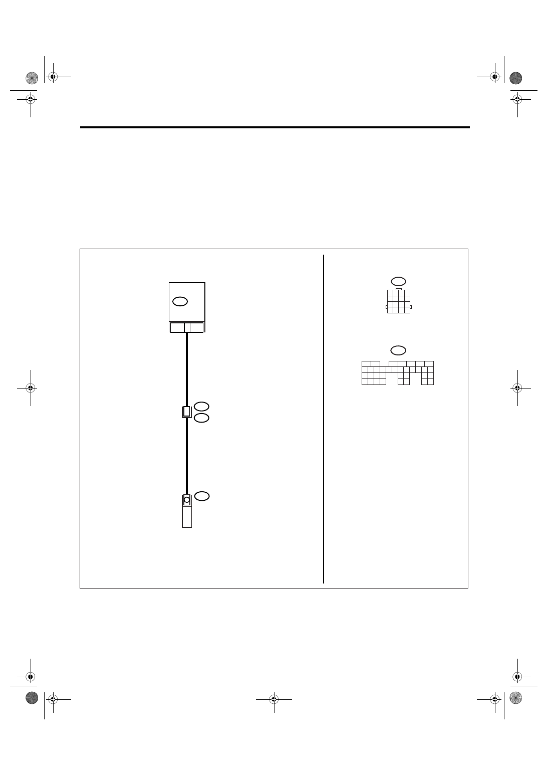
WIRING DIAGRAM:
EN-02512
B135
E71
21
B20
E1
9
ECM
VARIABLE VALVE LIFT DIAGNOSIS
OIL PRESSURE SWITCH RH
B135
5
6
7
8
2
1
9
4
3
10
24
22 23
25
11 12 13 14 15
26 27
28
16 17 18 19
20 21
29 30 31
32 33
34 35
B20
1 2 3 4
5 6 7 8
9 10 11 12
13 14 15 16
EN(H6DO)(diag)-75
ENGINE (DIAGNOSTICS)
Diagnostic Procedure with Diagnostic Trouble Code (DTC)
Step
Check
Yes
No
1
CHECK ANY OTHER DTC ON DISPLAY.
Is any other DTC displayed?
Check DTC using
the List of Diag-
nostic Trouble
Code (DTC). <Ref.
to
EN(H6DO)(diag)-
66, List of Diag-
nostic Trouble
Code (DTC).>
2
CHECK HARNESS BETWEEN ECM AND
VARIABLE VALVE LIFT DIAGNOSIS OIL
PRESSURE SWITCH CONNECTOR.
1) Idle the engine.
2) Turn the ignition switch to OFF.
3) Disconnect the connectors from ECM and
variable valve lift diagnosis oil pressure switch
connector.
4) Measure the resistance of harness
between variable valve lift diagnosis oil pres-
sure switch connector and engine ground.
Connector & terminal
(E71) No. 1 — Engine ground:
Is the resistance more than 1
M
Ω?
Repair the ground
short circuit of har-
ness between
ECM and variable
valve lift diagnosis
oil pressure switch
connector.
3
CHECK HARNESS BETWEEN ECM AND
VARIABLE VALVE LIFT DIAGNOSIS OIL
PRESSURE SWITCH CONNECTOR.
Measure the resistance in harness between
ECM and variable valve lift diagnosis oil pres-
sure switch connector.
Connector & terminal
(B135) No. 21 — (E71) No. 1:
Is the resistance less than 1
Ω?
Replace the vari-
able valve lift diag-
nosis oil pressure
switch. <Ref. to
FU(H6DO)-28,
Variable Valve Lift
Diagnosis Oil
Pressure Switch.>
Go to step 4.
Repair the open
circuit of harness
between ECM and
variable valve lift
diagnosis oil pres-
sure switch con-
nector.
4
CHECK DTC.
1) Perform the clear memory mode. <Ref. to
EN(H6DO)(diag)-41, Clear Memory Mode.>
2) Check the DTC after idling the engine.
Is DTC displayed?
Replace the oil
switching solenoid
valve. <Ref. to
ME(H6DO)-80, Oil
Switching Sole-
noid Valve.> Go to
step 5.
Temporary poor
contact occurs.
5
CHECK DTC.
1) Perform the clear memory mode. <Ref. to
EN(H6DO)(diag)-41, Clear Memory Mode.>
2) Check the DTC after idling the engine.
Is DTC displayed?
Check for oil rout-
ing.
Contact the SUB-
ARU dealer.
Temporary poor
contact occurs.

EN(H6DO)(diag)-76
ENGINE (DIAGNOSTICS)
Diagnostic Procedure with Diagnostic Trouble Code (DTC)
D: DTC P0028 INTAKE VALVE CONTROL SOLENOID CIRCUIT RANGE/PER-
FORMANCE (BANK 2)
DTC DETECTING CONDITION:
Immediately at fault recognition
TROUBLE SYMPTOM:
Erroneous idling
CAUTION:
After repair or replacement of faulty parts, conduct Clear Memory Mode <Ref. to EN(H6DO)(diag)-41,
OPERATION, Clear Memory Mode.> and Inspection Mode <Ref. to EN(H6DO)(diag)-34, PROCEDURE,
Inspection Mode.>.
WIRING DIAGRAM:
EN-02513
B135
29
B20
E1
10
ECM
B135
5
6
7
8
2
1
9
4
3
10
24
22 23
25
11 12 13 14 15
26 27
28
16 17 18 19
20 21
29 30 31
32 33
34 35
B20
1 2 3 4
5 6 7 8
9 10 11 12
13 14 15 16
1
E72
VARIABLE VALVE LIFT DIAGNOSIS
OIL PRESSURE SWITCH LH
Нет комментариевНе стесняйтесь поделиться с нами вашим ценным мнением.
Текст