Subaru Legacy (2005 year). Service manual — part 441

EN(H6DO)(diag)-77
ENGINE (DIAGNOSTICS)
Diagnostic Procedure with Diagnostic Trouble Code (DTC)
Step
Check
Yes
No
1
CHECK ANY OTHER DTC ON DISPLAY.
Is any other DTC displayed?
Check DTC using
the List of Diag-
nostic Trouble
Code (DTC). <Ref.
to
EN(H6DO)(diag)-
66, List of Diag-
nostic Trouble
Code (DTC).>
2
CHECK HARNESS BETWEEN ECM AND
VARIABLE VALVE LIFT DIAGNOSIS OIL
PRESSURE SWITCH CONNECTOR.
1) Idle the engine.
2) Turn the ignition switch to OFF.
3) Disconnect the connectors from ECM and
variable valve lift diagnosis oil pressure switch
connector.
4) Measure the resistance of harness
between variable valve lift diagnosis oil pres-
sure switch connector and engine ground.
Connector & terminal
(E72) No. 1 — Engine ground:
Is the resistance more than 1
M
Ω?
Repair the ground
short circuit of har-
ness between
ECM and variable
valve lift diagnosis
oil pressure switch
connector.
3
CHECK HARNESS BETWEEN ECM AND
VARIABLE VALVE LIFT DIAGNOSIS OIL
PRESSURE SWITCH CONNECTOR.
Measure the resistance in harness between
ECM and variable valve lift diagnosis oil pres-
sure switch connector.
Connector & terminal
(B135) No. 29 — (E72) No. 1:
Is the resistance less than 1
Ω?
Replace the vari-
able valve lift diag-
nosis oil pressure
switch. <Ref. to
FU(H6DO)-28,
Variable Valve Lift
Diagnosis Oil
Pressure Switch.>
Go to step 4.
Repair the open
circuit of harness
between ECM and
variable valve lift
diagnosis oil pres-
sure switch con-
nector.
4
CHECK DTC.
1) Perform the clear memory mode. <Ref. to
EN(H6DO)(diag)-41, Clear Memory Mode.>
2) Check the DTC after idling the engine.
Is DTC displayed?
Replace the oil
switching solenoid
valve. <Ref. to
ME(H6DO)-80, Oil
Switching Sole-
noid Valve.> Go to
step 5.
Temporary poor
contact occurs.
5
CHECK DTC.
1) Perform the clear memory mode. <Ref. to
EN(H6DO)(diag)-41, Clear Memory Mode.>
2) Check the DTC after idling the engine.
Is DTC displayed?
Check for oil rout-
ing.
Contact the SUB-
ARU dealer.
Temporary poor
contact occurs.
EN(H6DO)(diag)-78
ENGINE (DIAGNOSTICS)
Diagnostic Procedure with Diagnostic Trouble Code (DTC)
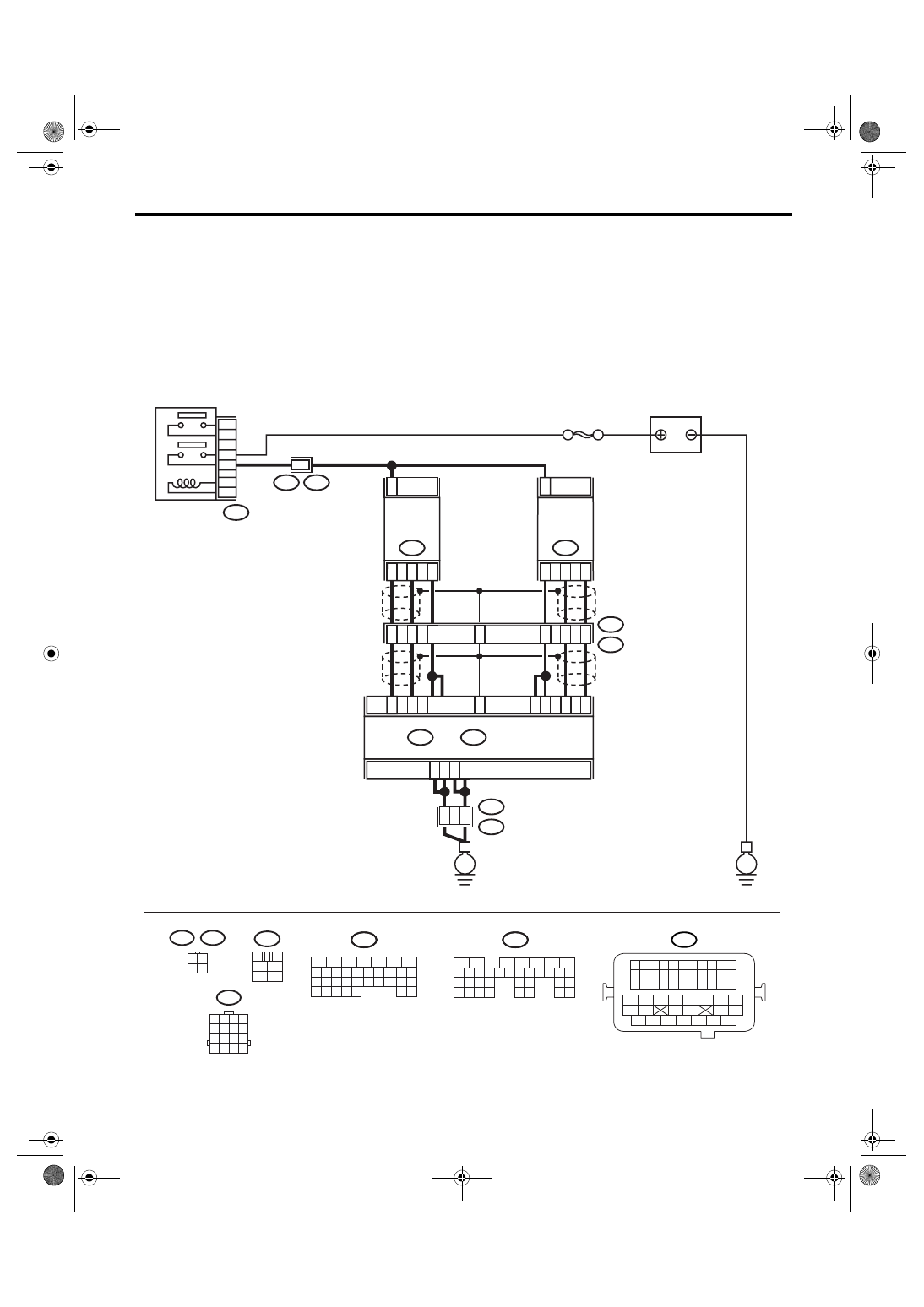
E: DTC P0030 HO2S HEATER CONTROL CIRCUIT (BANK 1 SENSOR 1)
DTC DETECTING CONDITION:
Detects when malfunction occurs in 2 continuous driving cycles.
CAUTION:
After repair or replacement of faulty parts, conduct Clear Memory Mode <Ref. to EN(H6DO)(diag)-41,
OPERATION, Clear Memory Mode.> and Inspection Mode <Ref. to EN(H6DO)(diag)-34, PROCEDURE,
Inspection Mode.>.
WIRING DIAGRAM:
BATTERY
SBF-5
B47
MAIN RELAY
A4
A5
A6
A7
2
52
54
B21
E2
ECM
A34
A27
B7
A1
A2
A3
A26
A33
4
1
3
FRONT
OXYGEN
(A/F)
SENSOR LH
E24
2
B135
B:
B134
A:
4
3
1
FRONT
OXYGEN
(A/F)
SENSOR RH
E47
E3
B22
8
5
6
E3
B22
2
1
3
4
B47
3
4
5
6
1
2
A25
B22
1 2 3 4
5 6 7 8
9 10 11 12
13 14 15 16
3 4
1 2
E47
E24
B135
5
6
7
8
2
1
9
4
3
10
24
22 23
25
11 12 13 14 15
26 27
28
16 17 18 19
20 21
29 30 31
32 33
34 35
B:
B134
5
6
7
8
2
1
9
4
3
10
24
22 23
25
11 12 13 14 15
26 27
28
16 17
18 19 20 21
33 34
29
32
30 31
A:
B21
1 2 3 4
12 13 14 15
5 6 7 8
16 17 18 19
9 10 11
20 21 22
23 24 25 26 27 28 29 30 31 32 33
35
34
37
36
39
38
41
40
43
42
44
45
47
46
49
48
51
50
53
52
54
E
E
EN-03494
B135
B:
B134
A:
7
5
3

EN(H6DO)(diag)-79
ENGINE (DIAGNOSTICS)
Diagnostic Procedure with Diagnostic Trouble Code (DTC)
Step
Check
Yes
No
1
CHECK HARNESS BETWEEN ECM AND
FRONT OXYGEN (A/F) SENSOR CONNEC-
TOR.
1) Start and warm-up the engine.
2) Turn the ignition switch to OFF.
3) Disconnect the connectors from ECM and
front oxygen (A/F) sensor.
4) Measure the resistance of harness
between ECM and front oxygen (A/F) sensor
connector.
Connector & terminal
(B134) No. 2 — (E47) No. 1:
(B134) No. 3 — (E47) No. 1:
Is the resistance less than 1
Ω?
Repair the open
circuit of harness
between ECM and
front oxygen (A/F)
sensor connector.
2
CHECK HARNESS BETWEEN ECM AND
FRONT OXYGEN (A/F) SENSOR CONNEC-
TOR.
Measure the resistance of harness between
ECM and front oxygen (A/F) sensor connector.
Connector & terminal
(B134) No. 26 — (E47) No. 4:
(B134) No. 33 — (E47) No. 3:
Is the resistance less than 1
Ω?
Repair the open
circuit of harness
between ECM and
front oxygen (A/F)
sensor connector.
3
CHECK HARNESS BETWEEN MAIN RELAY
AND FRONT OXYGEN (A/F) SENSOR CON-
NECTOR.
Measure the resistance of harness between
main relay and front oxygen (A/F) sensor con-
nector.
Connector & terminal
(B47) No. 3 — (E47) No. 2:
Is the resistance less than 1
Ω?
Repair the open
circuit of harness
between main
relay and front
oxygen (A/F) sen-
sor connector.
4
CHECK FRONT OXYGEN (A/F) SENSOR.
Measure the resistance between front oxygen
(A/F) sensor connector terminals.
Terminal
No. 2 — No. 1:
Is the resistance less than 5
Ω?
Replace the front
oxygen (A/F) sen-
sor. <Ref. to
FU(H6DO)-30,
Front Oxygen (A/
F) Sensor.>
5
CHECK POOR CONTACT.
Check poor contact in ECM and front oxygen
(A/F) sensor connector.
Is there poor contact in ECM or
front oxygen (A/F) sensor con-
nector?
Repair the poor
contact in ECM or
front oxygen (A/F)
sensor connector.
Replace the front
oxygen (A/F) sen-
sor. <Ref. to
FU(H6DO)-30,
Front Oxygen (A/
F) Sensor.>

EN(H6DO)(diag)-80
ENGINE (DIAGNOSTICS)
Diagnostic Procedure with Diagnostic Trouble Code (DTC)
F: DTC P0031 HO2S HEATER CONTROL CIRCUIT LOW (BANK 1 SENSOR 1)
DTC DETECTING CONDITION:
Immediately at fault recognition
CAUTION:
After repair or replacement of faulty parts, conduct Clear Memory Mode <Ref. to EN(H6DO)(diag)-41,
OPERATION, Clear Memory Mode.> and Inspection Mode <Ref. to EN(H6DO)(diag)-34, PROCEDURE,
Inspection Mode.>.
WIRING DIAGRAM:
BATTERY
SBF-5
B47
MAIN RELAY
A4
A5
A6
A7
2
52
54
B21
E2
ECM
A34
A27
B7
A1
A2
A3
A26
A33
4
1
3
FRONT
OXYGEN
(A/F)
SENSOR LH
E24
2
B135
B:
B134
A:
4
3
1
FRONT
OXYGEN
(A/F)
SENSOR RH
E47
E3
B22
8
5
6
E3
B22
2
1
3
4
B47
3
4
5
6
1
2
A25
B22
1 2 3 4
5 6 7 8
9 10 11 12
13 14 15 16
3 4
1 2
E47
E24
B135
5
6
7
8
2
1
9
4
3
10
24
22 23
25
11 12 13 14 15
26 27
28
16 17 18 19
20 21
29 30 31
32 33
34 35
B:
B134
5
6
7
8
2
1
9
4
3
10
24
22 23
25
11 12 13 14 15
26 27
28
16 17
18 19 20 21
33 34
29
32
30 31
A:
B21
1 2 3 4
12 13 14 15
5 6 7 8
16 17 18 19
9 10 11
20 21 22
23 24 25 26 27 28 29 30 31 32 33
35
34
37
36
39
38
41
40
43
42
44
45
47
46
49
48
51
50
53
52
54
E
E
EN-03494
B135
B:
B134
A:
7
5
3
Нет комментариевНе стесняйтесь поделиться с нами вашим ценным мнением.
Текст