Subaru Legacy (2005 year). Service manual — part 877
AC(diag)-25
HVAC SYSTEM (AUTO A/C) (DIAGNOSTICS)
Diagnostic Procedure for Actuators
Step
Check
Yes
No
1
CHECK POWER SUPPLY FOR INTAKE
DOOR ACTUATOR.
1) Turn the ignition switch to OFF.
2) Disconnect the intake door actuator con-
nector.
3) Turn the ignition switch to ON.
4) Measure the voltage between intake door
actuator connector and chassis ground.
Connector & terminal
(B91) No. 7 (+) — Chassis ground (
−
):
Is the voltage 7 V (at normal
temperature)?
Check the harness
for open or short
circuit between
intake door actua-
tor and fuse.
2
CHECK HARNESS BETWEEN AUTO A/C
CONTROL MODULE AND INTAKE DOOR
ACTUATOR.
1) Turn the ignition switch to OFF.
2) Disconnect the auto A/C control module
connector.
3) Measure the resistance between intake
door actuator connector and auto A/C control
module connector.
Connector & terminal
(B283) No. 10 — (B91) No. 3:
(B283) No. 20 — (B91) No. 1:
Is the resistance less than 1
Ω?
Repair the har-
ness between auto
A/C control mod-
ule and intake
door actuator.
3
CHECK OPERATION OF INTAKE DOOR AC-
TUATOR.
1) Connect the intake door actuator connec-
tor.
2) Ground the auto A/C control module con-
nector with a suitable wire.
3) Turn the ignition switch to ON, and check
the operation of intake door actuator.
Connector & terminal
(B283) No. 10 — Chassis ground:
Does the actuator move to the
FRESH side?
Replace the intake
door actuator.
4
CHECK OPERATION OF INTAKE DOOR AC-
TUATOR.
1) Turn the ignition switch to OFF.
2) Ground the auto A/C control module con-
nector with a suitable wire.
3) Turn the ignition switch to ON, and check
the operation of intake door actuator.
Connector & terminal:
(B283) No. 20 — Chassis ground:
Does the actuator move to the
RECIRC side?
Replace the auto
A/C control mod-
ule.
Replace the intake
door actuator.

AC(diag)-26
HVAC SYSTEM (AUTO A/C) (DIAGNOSTICS)
Diagnostic Procedure for Actuators
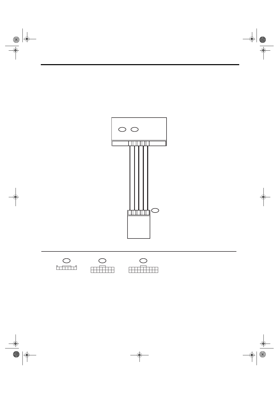
B: MODE DOOR ACTUATOR
TROUBLE SYMPTOM:
Air flow outlet is not changed.
WIRING DIAGRAM:
AC-00827
3 4
1 2
8 9 10
11 12 13 14 15 16 17 18 19 20
5 6 7
B77
B283
B:
3 4
1 2
8
9 10 11 12 13 14 15 16
5 6 7
B282
A:
B283
B282
B77
B17
AUTO A/C
CONTROL MODULE
MODE DOOR ACTUATOR
1
5
4
A15
B7
B:
A:
3
2
A8
A3
1 2 3 4 5
AC(diag)-27
HVAC SYSTEM (AUTO A/C) (DIAGNOSTICS)
Diagnostic Procedure for Actuators
Step
Check
Yes
No
1
CHECK POWER SUPPLY FOR MODE DOOR
ACTUATOR POSITION SENSOR.
1) Turn the ignition switch to OFF.
2) Disconnect the mode door actuator con-
nector.
3) Turn the ignition switch and AUTO switch to
ON.
4) Measure the voltage between auto A/C
control module connector terminals.
Connector & terminal
(B282) No. 8 (+) — (B282) No. 15 (
−
):
Is the voltage approx. 5 V?
Replace the auto
A/C control mod-
ule.
2
CHECK POWER SUPPLY FOR MODE DOOR
ACTUATOR.
Measure the voltage between auto A/C control
module connector and chassis ground after
turning the air flow control switch to FACE posi-
tion.
Connector & terminal
(B283) No. 7 (+) — Chassis ground (
−
):
Is the voltage 7 V (at normal
temperature)?
Replace the auto
A/C control mod-
ule.
3
CHECK POWER SUPPLY FOR MODE DOOR
ACTUATOR.
Measure the voltage between auto A/C control
module connector and chassis ground after
turning the air flow control switch to DEF posi-
tion.
Connector & terminal
(B283) No. 17 (+) — Chassis ground (
−
):
Is the voltage 7 V (at normal
temperature)?
Replace the auto
A/C control mod-
ule.
4
CHECK HARNESS BETWEEN AUTO A/C
CONTROL MODULE AND MODE DOOR AC-
TUATOR.
1) Turn the A/C and ignition switch to OFF.
2) Disconnect the auto A/C control module
connector.
3) Measure the resistance between auto A/C
control module and mode door actuator con-
nector.
Connector & terminal
(B77) No. 1 — (B282) No. 15:
(B77) No. 2 — (B282) No. 8:
(B77) No. 3 — (B282) No. 3:
(B77) No. 4 — (B283) No. 17:
(B77) No. 5 — (B283) No. 7:
Is the resistance less than 1
Ω?
Repair the har-
ness between auto
A/C control mod-
ule and mode door
actuator.
5
CHECK MODE DOOR ACTUATOR POSI-
TION SWITCH SIGNAL.
1) Connect the connector of auto A/C control
module and mode door actuator.
2) Turn the ignition switch and AUTO switch to
ON.
3) Check the voltage between auto A/C con-
trol module connector terminals while chang-
ing the mode between DEF and FACE.
Connector & terminal
(B282) No. 3 (+) — (B282) No. 15 (
−
):
Does the voltage change
between 1 (DEF) — 4 (FACE)
V?
Replace the mode
door actuator.
6
CHECK POOR CONTACT.
Check poor contact in auto A/C control module
and connector.
Is there poor contact in con-
nector?
Repair connector.
Replace the auto
A/C control mod-
ule.
AC(diag)-28
HVAC SYSTEM (AUTO A/C) (DIAGNOSTICS)
Diagnostic Procedure for Actuators
C: AIR MIX DOOR ACTUATOR
TROUBLE SYMPTOM:
Outlet air temperature does not change.
WIRING DIAGRAM:
AC-00828
3 4
1 2
8 9 10
11 12 13 14 15 16 17 18 19 20
5 6 7
B235
B283
B:
3 4
1 2
8
9 10 11 12 13 14 15 16
5 6 7
B282
A:
B283
B282
B235
B8
3
7
6
A15
B18
B:
A:
5
1
A8
A4
1
3 4 5
7
2
6
AUTO A/C
CONTROL MODULE
AIR MIX DOOR ACTUATOR
Нет комментариевНе стесняйтесь поделиться с нами вашим ценным мнением.
Текст