Subaru Legacy (2005 year). Service manual — part 875
AC(diag)-17
HVAC SYSTEM (AUTO A/C) (DIAGNOSTICS)
Diagnostics for A/C System Malfunction
9
CHECK AUTO A/C CONTROL MODULE
GROUND CIRCUIT.
Measure the resistance in harness between
auto A/C control module and chassis ground.
Connector & terminal
(B282) No. 14, No. 16 — Chassis ground:
Is the resistance less than 5
Ω?
Repair the har-
ness for ground
line.
10
CHECK COMMUNICATION CIRCUIT.
Measure the resistance in harness between A/
C control panel and auto A/C control module.
Connector & terminal
(i88) No. 3 — (B283) No. 16:
(i88) No. 7 — (B283) No. 15:
Is the resistance less than1
Repair the har-
ness.
11
CHECK POOR CONTACT.
Check poor contact in auto A/C control module
connector.
Is there poor contact in con-
nector?
Repair the con-
nector.
Replace the auto
A/C control mod-
ule.
Step
Check
Yes
No
AC(diag)-18
HVAC SYSTEM (AUTO A/C) (DIAGNOSTICS)
Diagnostics for A/C System Malfunction
B: BLOWER FAN DOES NOT ROTATE.
TROUBLE SYMPTOM:
• Blower motor does not rotate.
• Blower motor does not rotate in “HI”.
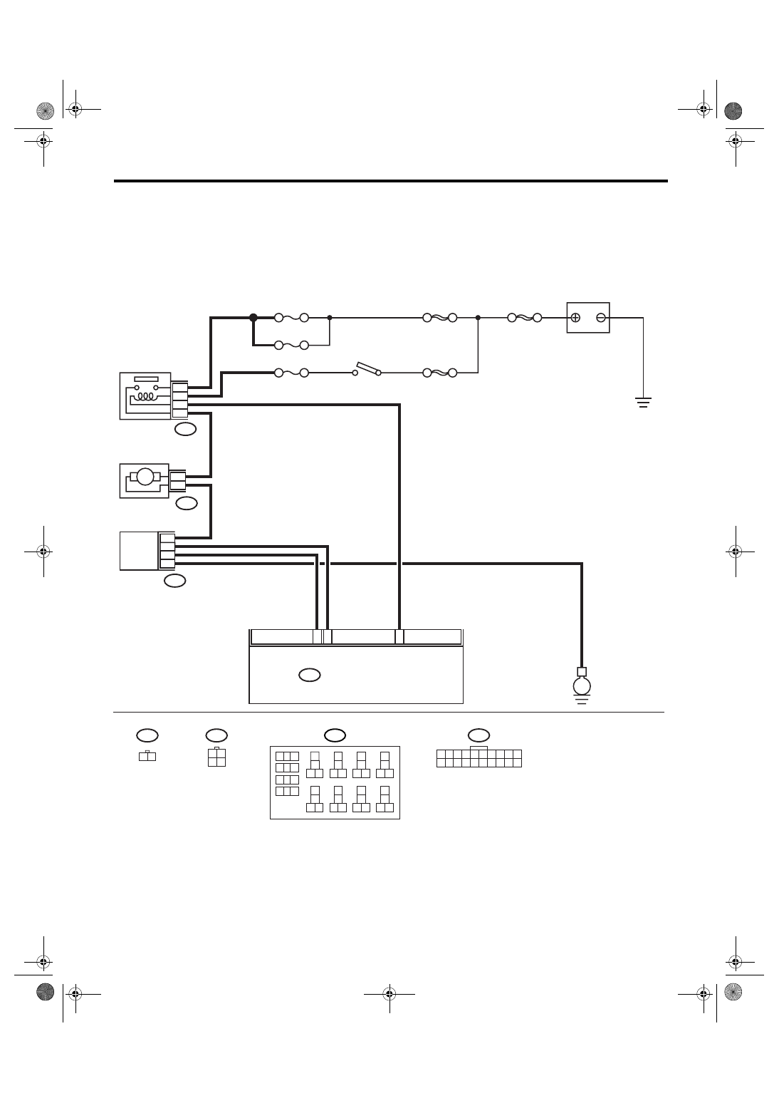
WIRING DIAGRAM:
B2
B3
B13
B225
B87
B86
BATTERY
F/B No. 27
F/B No. 28
F/B No. 22
SBF-3
MAIN SBF
SBF-6
B283
1 2 3 4 5 6 7 8 9 10
11 12 13 14 15 16 17 18 19 20
B:
2
4
1
22
24
23
21
2
1
BLOWER MOTOR
BLOWER MOTOR
RELAY
IGNITION
SWITCH
B87
B86
3 4
1 2
B283
B:
AUTO A/C CONTROL MODULE
AC-01249
E
M
3
1 2
9
10
1
2
3
4
5
6
7
8
11 12
14
15 16
13
18
19 20
17
22
23 24
21
38
39 40
37
34
35 36
33
30
31 32
29
26
27 28
25
B225
POWER
TRANSISTOR
AC(diag)-19
HVAC SYSTEM (AUTO A/C) (DIAGNOSTICS)
Diagnostics for A/C System Malfunction
Step
Check
Yes
No
1
CHECK FUSE.
1) Remove the fuse No. 22, 27 and 28 from
fuse & relay box.
2) Check the condition of fuse.
Is any fuse blown-out?
Replace the fuse.
2
CHECK POWER SUPPLY FOR BLOWER
MOTOR.
1) Turn the ignition switch to ON.
2) Turn the blower switch to ON.
3) Measure the voltage between blower motor
and chassis ground.
Connector & terminal
(B87) No. 2 (+) — Chassis ground (
−
):
Is the voltage more than 10 V? Go to step 3.
Repair the open
circuit of blower
motor power sup-
ply line harness.
3
CHECK BLOWER MOTOR RELAY.
1) Turn the ignition switch to OFF.
2) Remove the blower motor relay.
3) Connect the battery positive (+) terminal to
terminal No. 24 of blower motor relay, and neg-
ative (
−) terminal to terminal No. 23.
4) Measure the resistance between terminals
No. 21 and 22.
Terminals
No. 21 — No. 22:
Is the resistance less than 1
Ω?
Replace the
blower motor relay.
4
CHECK BLOWER MOTOR.
1) Disconnect the connector from blower
motor.
2) Connect the battery positive (+) terminal to
terminal No. 2 of blower motor connector, and
negative (
−) terminal to terminal No. 1.
3) Make sure the blower motor runs.
Does the blower motor run?
Replace the
blower motor.
5
CHECK POOR CONTACT.
Check poor contact in auto A/C control module
connector.
Is there poor contact in con-
nector?
Repair the con-
nector.
Replace the auto
A/C control mod-
ule.
AC(diag)-20
HVAC SYSTEM (AUTO A/C) (DIAGNOSTICS)
Diagnostics for A/C System Malfunction
C: COMPARTMENT TEMPERATURE DOES NOT CHANGE, OR A/C SYSTEM
DOES NOT RESPOND PROMPTLY.
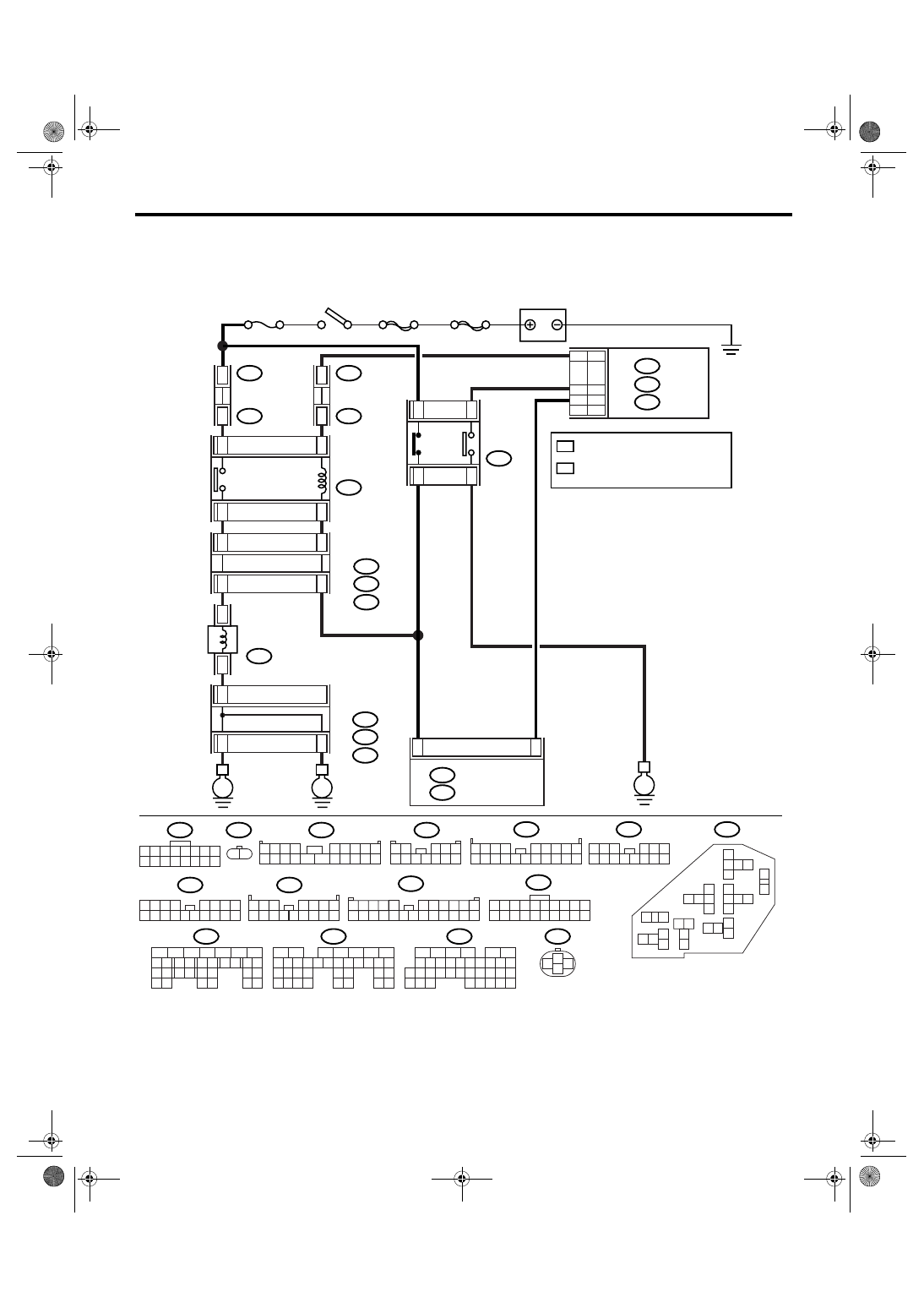
WIRING DIAGRAM:
AC-01250
MAIN SBF
SBF-6
F/B No.22
B360
F109
B143
B:
F37
A:
F35
C:
1
9
ND
HU
F24
1
2
B361
F108
B135
B136
B137
B:
C:
D:
ECM
B283
B:
B282
A:
B282
B10
F24
A:
B283
B:
B137
D:
B143
B360
F109
F108
B:
F37
A:
F35
F27
C:
B143
B:
F37
A:
F35
C:
F27
B10
14
9
28
30
29
31
E
E
C3
C7
A4
B13
2
4
1
3
HU
B20
C8
B33 B35
ND
D17
C30
A10
B6
E
A13
B20
C12
1 2 3 4 5 6 7 8
9 10 11 12 13 14 15 16
1 2
1 2 3 4
5 6 7 8 9
10 11 12 13 14
15 16 17 18 19 20
1 2
3 4 5
6 7 8 9 10 11 12
2
3
1
4
2 3 4
5 6 7 8 9
11 12 13 14
17 18 19 20
1
10
15 16
B361
1 2 3
4 5 6
7 8 9 10 11 12 13 14
1 2 3
8
9 10
4
11 12 13 14 15 16
5 6 7
17 18
1 2 3
8 9 10
4
11 12 13 14 15 16
5 6 7
1
2
3
6
7
4 5
13
14
15
11
30
31
16 17
8 9 10
12
26
27
18
19
29 28
22
23
20 21
24 25
3 4
1 2
8 9 10 11
12 13 14 15 16 17 18 19 20 21 22 23 24
5
6 7
1 2 3 4 5 6 7 8 9 10
11 12 13 14 15 16 17 18 19 20
1
2
7
8 9
5
6
3
4
10 11 12
19 20 21
29
30 31
13 14 15 16 17
27
28
18
22 23
24 25
26
B135
B:
1
2
7
8 9
5
6
3
4
10 11 12
19
20 21
29 30 31
13 14 15 16 17
27
28
18
22 23
24 25
26
32 33
34 35
B136
C:
1
2
8 9
5
6
3
4
10 11 12
19 20 21
29 30
31
13 14 15 16
17
27
28
18
22 23 24 25 26
7
32 33 34 35
AUTO A/C
CONTROL MODULE
: 2.0 L TURBO MODEL, 3.0 L MODEL
AND 2.5 L EC, K4, EK MODEL
: 2.0 L NON-TURBO MODEL
AND 2.5 L KS, KA MODEL
A/C RELAY
BATTERY
IGNITION SWITCH
THROUGH JOINT
CONNECTOR
THROUGH JOINT
CONNECTOR
PRESSURE
SWITCH
MAIN FUSE BOX
MAIN FUSE BOX
MAGNET
CLUTCH
Нет комментариевНе стесняйтесь поделиться с нами вашим ценным мнением.
Текст