Subaru Legacy (2005 year). Service manual — part 796
VDC(diag)-49
VEHICLE DYNAMICS CONTROL (VDC) (DIAGNOSTICS)
Diagnostic Procedure with Diagnostic Trouble Code (DTC)
Step
Check
Yes
No
1
CHECK POOR CONTACT IN CONNECTOR.
Check if there is poor contact between
VDCCM&H/U and ABS wheel speed sensor.
Is there poor contact?
Repair the con-
nector.
2
CHECK HARNESS CONNECTOR BETWEEN
VDCCM&H/U AND ABS WHEEL SPEED
SENSOR.
1) Disconnect the connector (B310) from
VDCCM&H/U.
2) Disconnect the connector from ABS wheel
speed sensor.
3) Measure the resistance between
VDCCM&H/U connector and ABS wheel
speed sensor connector.
Connector & terminal
DTC C0021
(B310) No. 22 — (B6) No. 1:
(B310) No. 21 — (B6) No. 2:
DTC C0023
(B310) No. 41 — (B15) No. 1:
(B310) No. 25 — (B15) No. 2:
DTC C0025
(B310) No. 23 — (R72) No. 1:
(B310) No. 38 — (R72) No. 2:
DTC C0027
(B310) No. 24 — (R73) No. 1:
(B310) No. 40 — (R73) No. 2:
Is the resistance less than 0.5
Ω?
Repair the har-
ness connector
between
VDCCM&H/U and
ABS wheel speed
sensor.
3
CHECK GROUND SHORT OF HARNESS.
Measure the resistance between VDCCM&H/U
connector and chassis ground.
Connector & terminal
DTC C0021
(B310) No. 21 — Chassis ground:
DTC C0023
(B310) No. 25 — Chassis ground:
DTC C0025
(B310) No. 38 — Chassis ground:
DTC C0027
(B310) No. 40 — Chassis ground:
Is the resistance more than 1
M
Ω?
Repair the har-
ness connector
between
VDCCM&H/U and
ABS wheel speed
sensor.
4
CHECK ABS WHEEL SPEED SENSOR POW-
ER SUPPLY CIRCUIT.
1) Connect the VDCCM&H/U connector.
2) Turn the ignition switch to ON.
3) Measure the voltage between ABS wheel
speed sensor connector and chassis ground.
Connector & terminal
DTC C0021
(B6) No. 1 (+) — Chassis ground (
−
):
DTC C0023
(B15) No. 1 (+) — Chassis ground (
−
):
DTC C0025
(R72) No. 1 (+) — Chassis ground (
−
):
DTC C0027
(R73) No. 1 (+) — Chassis ground (
−
):
Is the voltage 5 — 16 V?

VDC(diag)-50
VEHICLE DYNAMICS CONTROL (VDC) (DIAGNOSTICS)
Diagnostic Procedure with Diagnostic Trouble Code (DTC)
5
CHECK VDCCM&H/U POWER SUPPLY CIR-
CUIT.
1) Turn the ignition switch to OFF.
2) Disconnect the VDCCM&H/U connector.
3) Turn the ignition switch to ON.
4) Measure the voltage between VDCCM&H/
U connector terminals.
Connector & terminal
(B310) No. 14 (+) — (B310) No. 6 (
−
):
Is the voltage 10 — 15 V?
Check the genera-
tor, battery and
VDCCM&H/U
power supply cir-
cuit.
6
CHECK ABS WHEEL SPEED SENSOR SIG-
NAL.
1) Install the ABS wheel speed sensor.
2) Prepare an oscilloscope.
3) Check the ABS wheel speed sensor. <Ref.
to ABS-15, ABS WHEEL SPEED SENSOR,
INSPECTION, Rear ABS Wheel Speed Sen-
sor.>
Does the oscilloscope indicate
the waveform pattern like
shown in the figure when the
tire is slowly turned? Does the
oscilloscope indication repeat
the waveform pattern like
shown in the figure when the
tire is slowly turned in equal
speed for more one rotation?
7
CHECK ABS WHEEL SPEED SENSOR OR
MAGNETIC ENCODER.
Are there foreign materials,
breakage or damage in the
protrusion of ABS wheel speed
sensor or magnetic encoder?
Remove dirt
throughly. Also
replace the ABS
wheel speed sen-
sor or magnetic
encoder as a unit
with hub unit bear-
ing if it is broken or
damaged.
8
CHECK VDCCM&H/U.
1) Connect all the connectors.
2) Perform the clear memory mode.
3) Perform the inspection mode. <Ref. to
VDC(diag)-24, PROCEDURE, Inspection
Mode.>
4) Read the DTC.
Is the same DTC displayed?
Replace the
VDCCM&H/U.
<Ref. to VDC-7,
VDC Control Mod-
ule and Hydraulic
Control Unit
(VDCCM&H/U).>
9
CHECK OTHER DTC DETECTION.
Is any other DTC displayed?
Perform the diag-
nosis according to
DTC.
It results from a
temporary noise
interference.
Step
Check
Yes
No
VDC(diag)-51
VEHICLE DYNAMICS CONTROL (VDC) (DIAGNOSTICS)
Diagnostic Procedure with Diagnostic Trouble Code (DTC)
I:
DTC C0022 FRONT ABS WHEEL SPEED SENSOR RH SIGNAL MALFUNC-
TION
NOTE:
For the diagnostic procedure, refer to DTC C0028 “REAR ABS WHEEL SPEED SENSOR LH SIGNAL MAL-
FUNCTION”. <Ref. to VDC(diag)-51, DTC C0028 REAR ABS WHEEL SPEED SENSOR LH SIGNAL MAL-
FUNCTION, Diagnostic Procedure with Diagnostic Trouble Code (DTC).>
J: DTC C0024 FRONT ABS WHEEL SPEED SENSOR LH SIGNAL MALFUNC-
TION
NOTE:
For the diagnostic procedure, refer to DTC C0028 “REAR ABS WHEEL SPEED SENSOR LH SIGNAL MAL-
FUNCTION”. <Ref. to VDC(diag)-51, DTC C0028 REAR ABS WHEEL SPEED SENSOR LH SIGNAL MAL-
FUNCTION, Diagnostic Procedure with Diagnostic Trouble Code (DTC).>
K: DTC C0026 REAR ABS WHEEL SPEED SENSOR RH SIGNAL MALFUNC-
TION
NOTE:
For the diagnostic procedure, refer to DTC C0028 “REAR ABS WHEEL SPEED SENSOR LH SIGNAL MAL-
FUNCTION”. <Ref. to VDC(diag)-51, DTC C0028 REAR ABS WHEEL SPEED SENSOR LH SIGNAL MAL-
FUNCTION, Diagnostic Procedure with Diagnostic Trouble Code (DTC).>
L: DTC C0028 REAR ABS WHEEL SPEED SENSOR LH SIGNAL MALFUNC-
TION
DTC DETECTING CONDITION:
• Defective ABS wheel speed sensor signal (noise, irregular signal, etc.)
• Defective harness connector
TROUBLE SYMPTOM:
• ABS does not operate.
• VDC does not operate.
VDC(diag)-52
VEHICLE DYNAMICS CONTROL (VDC) (DIAGNOSTICS)
Diagnostic Procedure with Diagnostic Trouble Code (DTC)
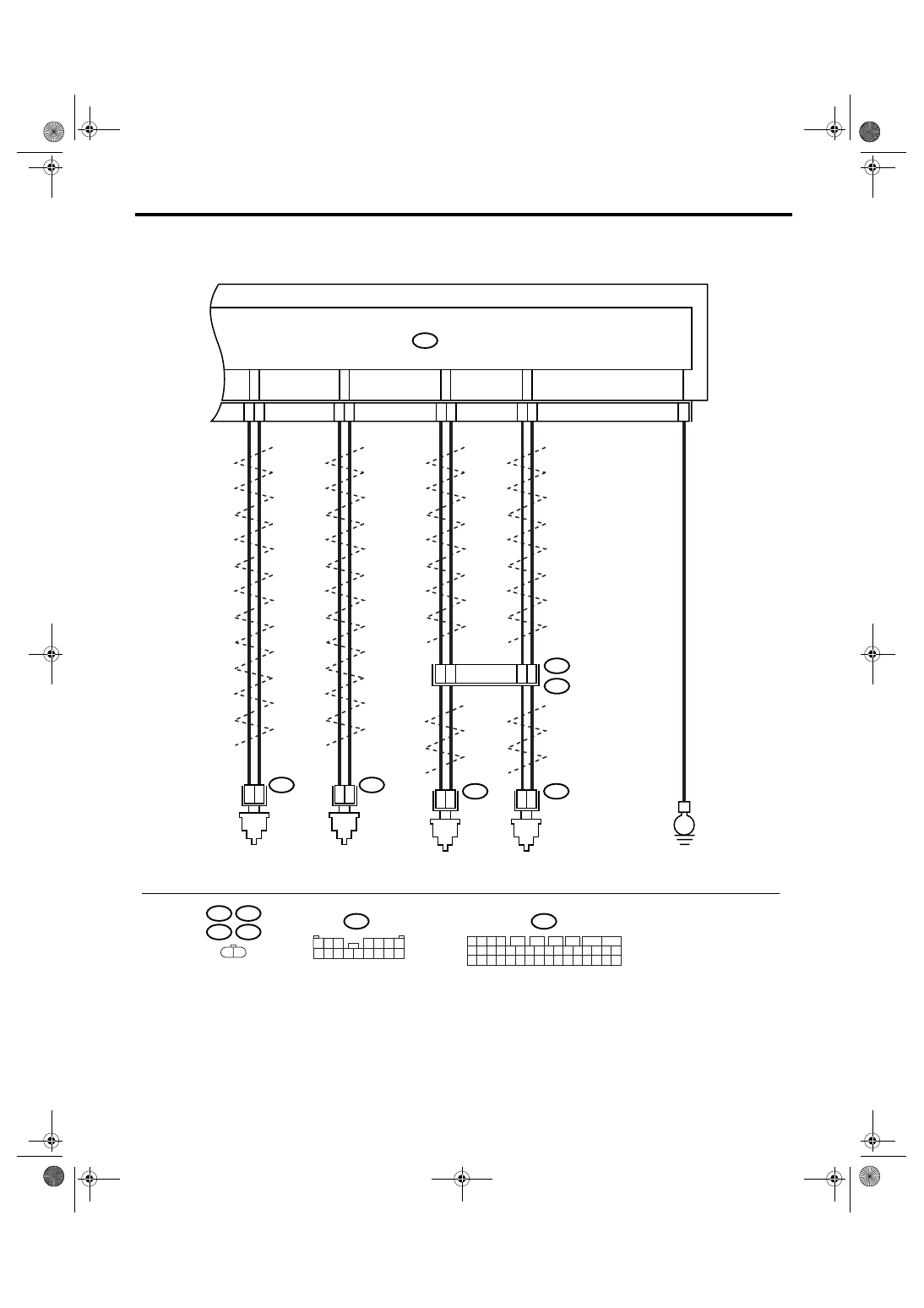
WIRING DIAGRAM:
• LHD model
B15
B6
R73
R72
B310
B98
1 2 3 4
11 12 13 14
27 28 29 30
15 16 17 18
31 32 33 34
19 20 21 22
35 36 37 38
23 24 25 26
39 40 41 42
5
6
7
8
9
10
VDC00299
38
23
25
41
40
24
6
B98
R72
R2
E
1
2
15
14
6
5
R73
1
2
1
2
1
2
B6
B15
21
22
B310
VDCCM & H/U
TWISTED WIRE
FRONT ABS
WHEEL SPEED
SENSOR LH
TWISTED WIRE
TWISTED WIRE
TWISTED WIRE
FRONT ABS
WHEEL SPEED
SENSOR RH
REAR ABS
WHEEL SPEED
SENSOR LH
REAR ABS
WHEEL SPEED
SENSOR RH
1 2
1 2 3
4 5 6 7
8 9 10 11 12 13 14 15 16
Нет комментариевНе стесняйтесь поделиться с нами вашим ценным мнением.
Текст