Subaru Legacy (2005 year). Service manual — part 596
5AT-83
AUTOMATIC TRANSMISSION
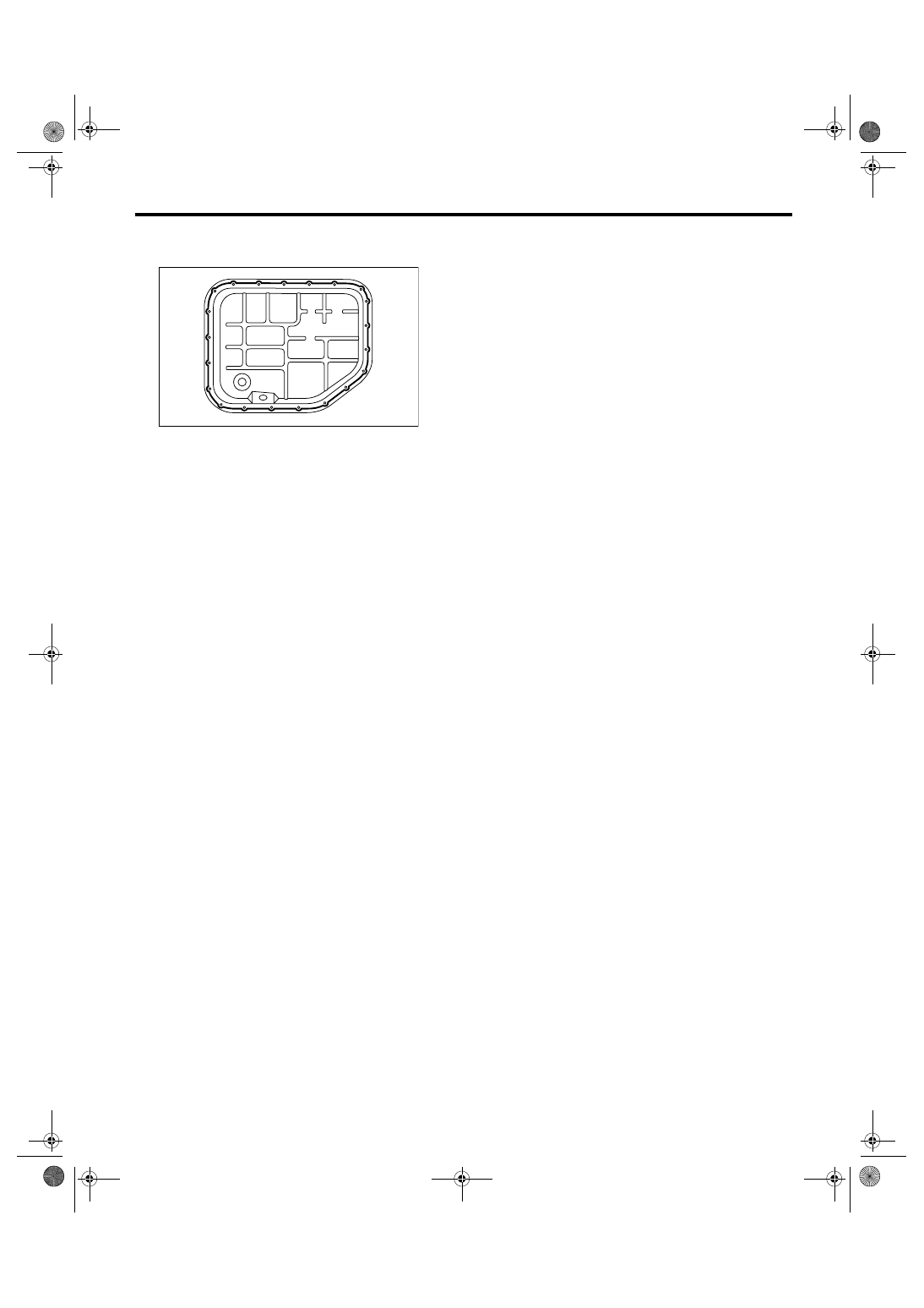
Converter Case
Tightening torque:
5 N
⋅
m (0.5 kgf-m, 3.7 ft-lb)
9) Install the transmission harness connector to the
stay.
10) Install the air breather hose. <Ref. to 5AT-68,
INSTALLATION, Air Breather Hose.>
11) Install the ATF filter pipe. <Ref. to 5AT-60, IN-
STALLATION, ATF Filter.>
12) Install the oil charge pipe with O-ring. <Ref. to
5AT-69, INSTALLATION, Oil Charge Pipe.>
13) Install the torque converter assembly. <Ref. to
5AT-70, INSTALLATION, Torque Converter As-
sembly.>
14) Install the transmission assembly into vehicle.
<Ref. to 5AT-42, INSTALLATION, Automatic
Transmission Assembly.>
C: INSPECTION
Measure the backlash, and then adjust it within
specification. <Ref. to 5AT-89, ADJUSTMENT,
Drive Pinion Shaft Assembly.>
AT-01955
5AT-84
AUTOMATIC TRANSMISSION
Oil Pump Cover
32.Oil Pump Cover
A: REMOVAL
1) Remove the transmission assembly from vehi-
cle. <Ref. to 5AT-38, REMOVAL, Automatic Trans-
mission Assembly.>
2) Pull out the torque converter assembly. <Ref. to
5AT-70, REMOVAL, Torque Converter Assembly.>
3) Remove the transmission harness connector
from stay.
4) Remove the oil charge pipe. <Ref. to 5AT-69,
REMOVAL, Oil Charge Pipe.>
5) Remove the ATF filter inlet and outlet pipes.
<Ref. to 5AT-60, REMOVAL, ATF Filter.>
6) Separate the converter case and transmission
case part. <Ref. to 5AT-82, REMOVAL, Converter
Case.>
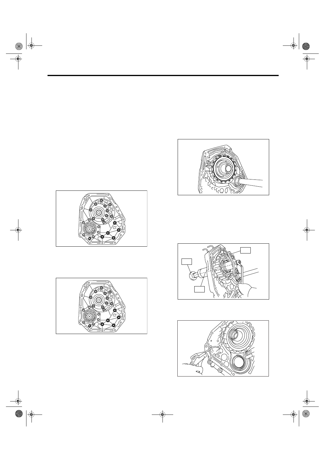
7) Remove the oil pump cover mounting bolt, and
then separate the oil pump cover from the AT main
case by lightly tapping with plastic hammer.
B: INSTALLATION
1) Secure the oil pump cover.
Tightening torque:
41 N
⋅
m (4.2 kgf-m, 30.2 ft-lb)
2) Install the converter case assembly into trans-
mission case assembly. <Ref. to 5AT-70, INSTAL-
LATION, Torque Converter Assembly.>
3) Install the transmission harness connector to the
stay.
4) Install the ATF filter pipe. <Ref. to 5AT-60, IN-
STALLATION, ATF Filter.>
5) Install the oil charge pipe with a O-ring. <Ref. to
5AT-69, INSTALLATION, Oil Charge Pipe.>
6) Install the torque converter assembly. <Ref. to
5AT-70, INSTALLATION, Torque Converter As-
sembly.>
7) Install the transmission assembly into vehicle.
<Ref. to 5AT-42, INSTALLATION, Automatic
Transmission Assembly.>
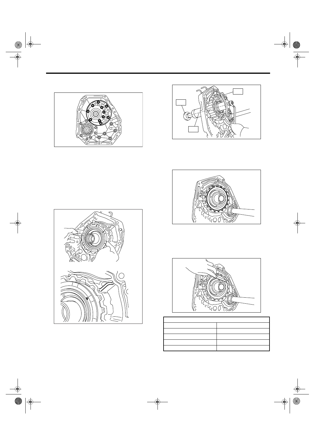
C: DISASSEMBLY
1. FRONT BRAKE
1) Remove the snap ring.
2) Remove the retainer plate, drive plate and driven
plate.
3) Using the ST1, ST2 and ST3, remove the snap
ring.
ST1
18762AA000 COMPRESSOR SPECIAL
TOOL
ST2
18765AA000 COMPRESSOR SUPPORT
ST3
18763AA000 COMPRESSOR SHAFT
4) Remove the retainer and return spring.
5) Remove the front brake piston using com-
pressed air.
6) Remove the D-ring from front brake piston.
AT-01976
AT-01976
AT-01980
AT-01981
ST1
ST2
ST3
AT-02349
5AT-85
AUTOMATIC TRANSMISSION
Oil Pump Cover
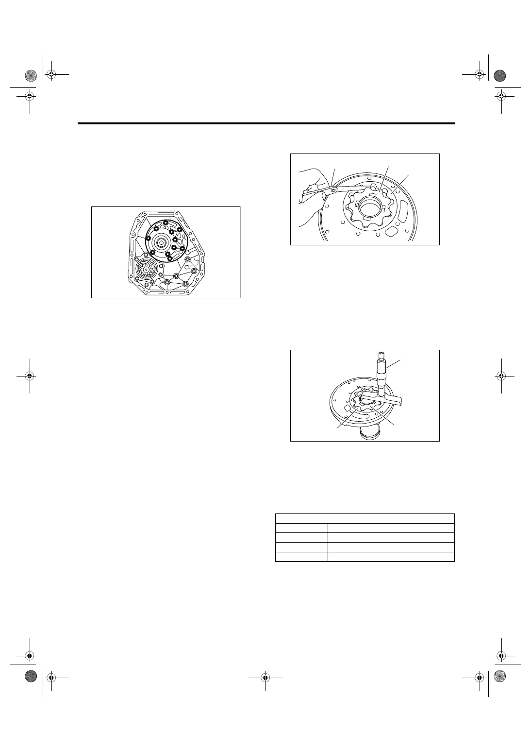
2. OIL PUMP
1) Take out the oil pump housing.
2) Take out the oil pump body.
D: ASSEMBLY
1. FRONT BRAKE
1) Apply ATF to D-ring, and then install it to the
front brake piston.
2) Install the front brake piston to oil pump cover.
NOTE:
Install by aligning the “
▲” mark on front brake pis-
ton surface with the oil pump cover rib.
3) Install the retainer and return spring.
4) Install the front brake piston assembly using
ST1, ST2 and ST3.
ST1
18762AA000 COMPRESSOR SPECIAL
TOOL
ST2
18765AA000 COMPRESSOR SUPPORT
ST3
18763AA000 COMPRESSOR SHAFT
5) Install the genuine driven plate instead of retain-
er plate, and temporarily assemble the drive plate
and driven plate.
Part No. 31536AA290
DRIVEN PLATE
6) Install the snap ring.
7) Measure the clearance between retainer plate
and snap ring, and then select the suitable retainer
plate from table.
Front brake clearance specification:
0.7 — 1.1 mm (0.028 — 0.043 in)
8) Remove the snap ring, replace the drive plate
which used in measurement of clearance with re-
tainer plate, and then reassemble.
AT-01982
AT-02350
Front brake retainer plate
Part No.
Thickness mm (in)
31567AB130
3.4 (0.134)
31567AB140
3.6 (0.142)
31567AB150
3.8 (0.150)
31567AB160
4.0 (0.157)
AT-01981
ST1
ST2
ST3
AT-01980
AT-01983
5AT-86
AUTOMATIC TRANSMISSION
Oil Pump Cover
2. OIL PUMP
1) Apply ATF to oil pump assembly, and then install
it to oil pump housing.
2) Install the O-ring to oil pump cover.
3) Install the oil pump housing to oil pump cover.
Tightening torque:
10 N
⋅
m (1.0 kgf-m, 7.4 ft-lb)
E: INSPECTION
1. FRONT BRAKE
Check the following items.
• Drive plate facing for wear and damage
• Snap ring for wear, return spring for damage,
and retainer for damage
• Piston for damage
• D-ring for damage
2. OIL PUMP
Check the following items.
• Oil pump cover and oil seal for breakage or dam-
age
• Oil pump body for scratch or damage
1) Check the seal ring and oil seal for breaks or
damages.
2) Check other parts for dents or abnormalities.
3) Selection of oil pump rotor assembly
(1) Tip clearance
Install the inner rotor and outer rotor to oil pump
housing. With rotor gears facing each other,
measure the crest-to-crest clearance.
Tip clearance:
0.02 — 0.15 mm (0.0008 — 0.0059 in)
(2) Side clearance
Set a depth gauge to oil pump housing, then
measure the oil pump housing-to-rotor clear-
ance.
Side clearance:
0.02 — 0.045 mm (0.0008 — 0.0018 in)
(3) If the depth and/or side clearance are not
within the specification, replace the rotor assem-
bly.
Measure the total end play and adjust it within
specification. <Ref. to 5AT-105, ADJUSTMENT,
AT Main Case.>
AT-01982
(A) Thickness gauge
(B) Inner rotor
(C) Outer rotor
(A) Depth gauge
(B) Inner rotor
(C) Outer rotor
Oil pump rotor ASSY
Part No.
Thickness mm (in)
15008AA130
11.37 — 11.38 (0.4476 — 0.4480)
15008AA140
11.38 — 11.39 (0.4480 — 0.4484)
15008AA150
11.39 — 11.40 (0.4484 — 0.4488)
AT-01977
(A)
(B)
(C)
AT-01978
(A)
(C)
(B)
Нет комментариевНе стесняйтесь поделиться с нами вашим ценным мнением.
Текст