Subaru Legacy (2005 year). Service manual — part 120
EN(H4SO 2.0)(diag)-69
ENGINE (DIAGNOSTICS)
Diagnostic Procedure with Diagnostic Trouble Code (DTC)
18.Diagnostic Procedure with Diagnostic Trouble Code (DTC)
A: DTC P0030 HO2S HEATER CONTROL CIRCUIT (BANK 1 SENSOR 1)
DTC DETECTING CONDITION:
Detects when malfunction occurs in 2 continuous driving cycles.
CAUTION:
After repair or replacement of faulty parts, perform Clear Memory Mode <Ref. to EN(H4SO 2.0)(diag)-
38, OPERATION, Clear Memory Mode.> and Inspection Mode <Ref. to EN(H4SO 2.0)(diag)-32, PRO-
CEDURE, Inspection Mode.>.
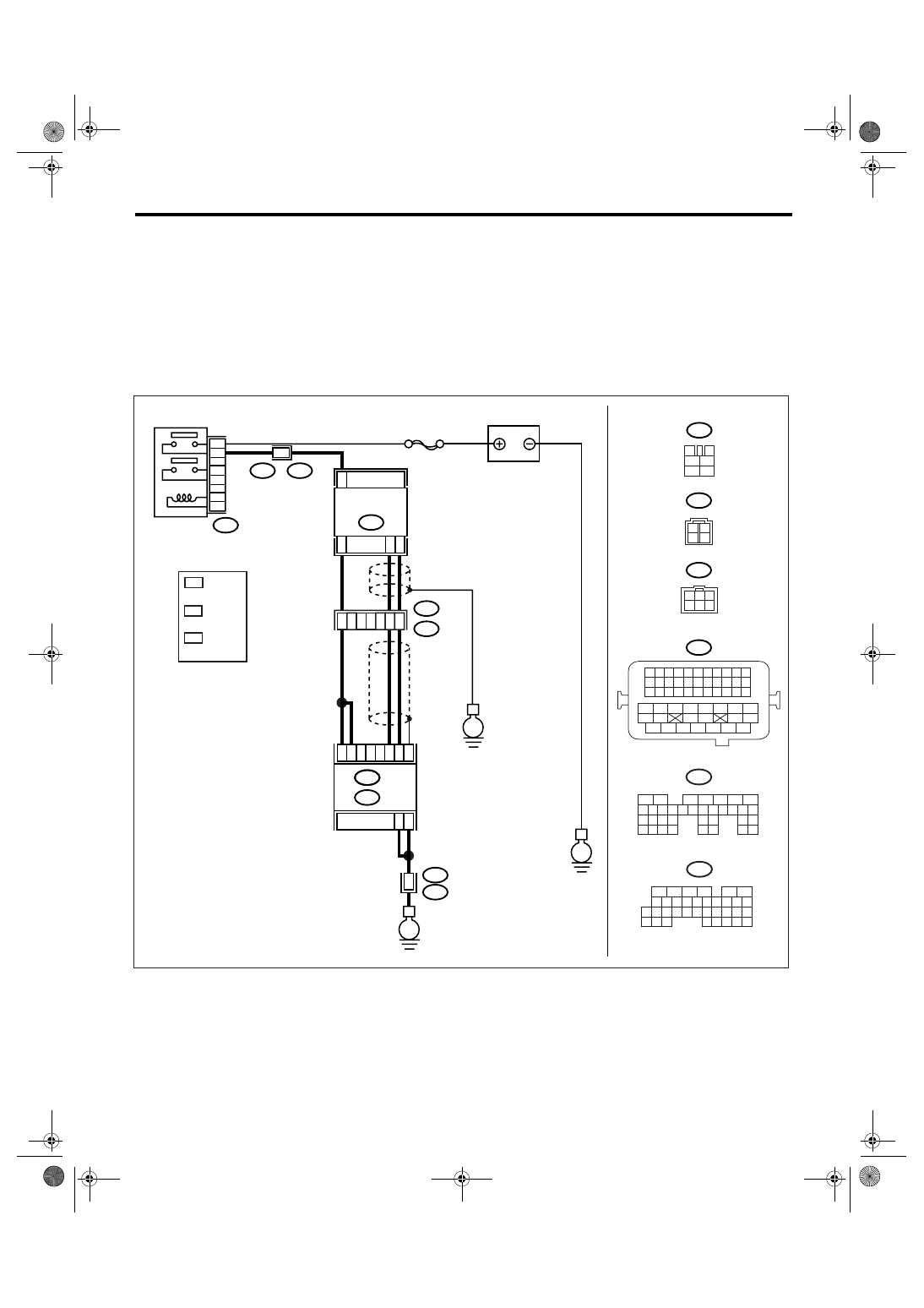
WIRING DIAGRAM:
EN-03475
3
4
1
2
5
6
B47
SBF-5
E
B47
E24
5
3
4
6
2
1
C34
C35
C33
B3
B2
B1
B135
E
B5
B6
52
B21
E2
B21
E2
50
51
3
4
E2
B21
E
B21
1 2 3 4
12 13 14 15
5 6 7 8
16 17 18 19
9 10 11
20 21 22
23 24 25 26 27 28 29 30 31 32 33
35
34
37
36
39
38
41
40
43
42
44
45
47
46
49
48
51
50
53
52
54
E24
ECM
BATTERY
FRONT OXYGEN
(A/F) SENSOR
MAIN RELAY
B136
B:
C:
1
2
3
4
B135
5
6
7
8
2
1
9
4
3
10
24
22 23
25
11 12 13 14 15
26 27
28
16 17 18 19
20 21
29 30 31
32 33
34 35
B:
B136
5
6
7 8
2
1
9
4
3
10
24
22 23
25
11 12 13 14 15
26 27
28
16
17 18 19 20 21
33 34
29
32
30
31
35
C:
E24
3
2
*
1
*
*
3
LHD : 4
RHD : 1
*
1
*
*
2
3
3
1
6 5 4
2
: RHD
: LHD
LHD : 1
RHD : 4
LHD : 2
RHD : 6

EN(H4SO 2.0)(diag)-70
ENGINE (DIAGNOSTICS)
Diagnostic Procedure with Diagnostic Trouble Code (DTC)
Step
Check
Yes
No
1
CHECK HARNESS BETWEEN ECM AND
FRONT OXYGEN (A/F) SENSOR CONNEC-
TOR.
1) Start and warm-up the engine.
2) Turn the ignition switch to OFF.
3) Disconnect the connectors from ECM and
front oxygen (A/F) sensor.
4) Measure the resistance of harness
between ECM and front oxygen (A/F) sensor
connector.
Connector & terminal
(B135) No. 2 — (E24) No. 3:
(B135) No. 3 — (E24) No. 3:
Is the resistance less than 1
Ω?
Repair the open
circuit of harness
between ECM and
front oxygen (A/F)
sensor connector.
2
CHECK HARNESS BETWEEN ECM AND
FRONT OXYGEN (A/F) SENSOR CONNEC-
TOR.
Measure the resistance of harness between
ECM and front oxygen (A/F) sensor connector.
Connector & terminal
LHD model
(B136) No. 33 — (E24) No. 1:
(B136) No. 35 — (E24) No. 2:
RHD model
(B136) No. 33 — (E24) No. 4:
(B136) No. 35 — (E24) No. 6:
Is the resistance less than 1
Ω?
Repair the open
circuit of harness
between ECM and
front oxygen (A/F)
sensor connector.
3
CHECK HARNESS BETWEEN MAIN RELAY
AND FRONT OXYGEN (A/F) SENSOR CON-
NECTOR.
Measure the resistance of harness between
main relay and front oxygen (A/F) sensor con-
nector.
Connector & terminal
LHD model
(B47) No. 3 — (E24) No. 4:
RHD model
(B47) No. 3 — (E24) No. 1:
Is the resistance less than 1
Ω?
Repair the open
circuit of harness
between ECM and
front oxygen (A/F)
sensor connector.
4
CHECK FRONT OXYGEN (A/F) SENSOR.
Measure the resistance between front oxygen
(A/F) sensor connector terminals.
Terminals
LHD model
No. 3 — No. 4:
RHD model
No. 1 — No. 3:
Is the resistance less than 5
Ω?
Replace the front
oxygen (A/F) sen-
sor. <Ref. to
FU(H4SO 2.0)-32,
Front Oxygen (A/
F) Sensor.>
5
CHECK POOR CONTACT.
Check poor contact in ECM and front oxygen
(A/F) sensor connector.
Is there poor contact in ECM or
front oxygen (A/F) sensor con-
nector?
Repair the poor
contact in ECM or
front oxygen (A/F)
sensor connector.
Replace the front
oxygen (A/F) sen-
sor. <Ref. to
FU(H4SO 2.0)-32,
Front Oxygen (A/
F) Sensor.>
EN(H4SO 2.0)(diag)-71
ENGINE (DIAGNOSTICS)
Diagnostic Procedure with Diagnostic Trouble Code (DTC)
B: DTC P0031 HO2S HEATER CONTROL CIRCUIT LOW (BANK 1 SENSOR 1)
DTC DETECTING CONDITION:
Immediately at fault recognition
CAUTION:
After repair or replacement of faulty parts, perform Clear Memory Mode <Ref. to EN(H4SO 2.0)(diag)-
38, OPERATION, Clear Memory Mode.> and Inspection Mode <Ref. to EN(H4SO 2.0)(diag)-32, PRO-
CEDURE, Inspection Mode.>.
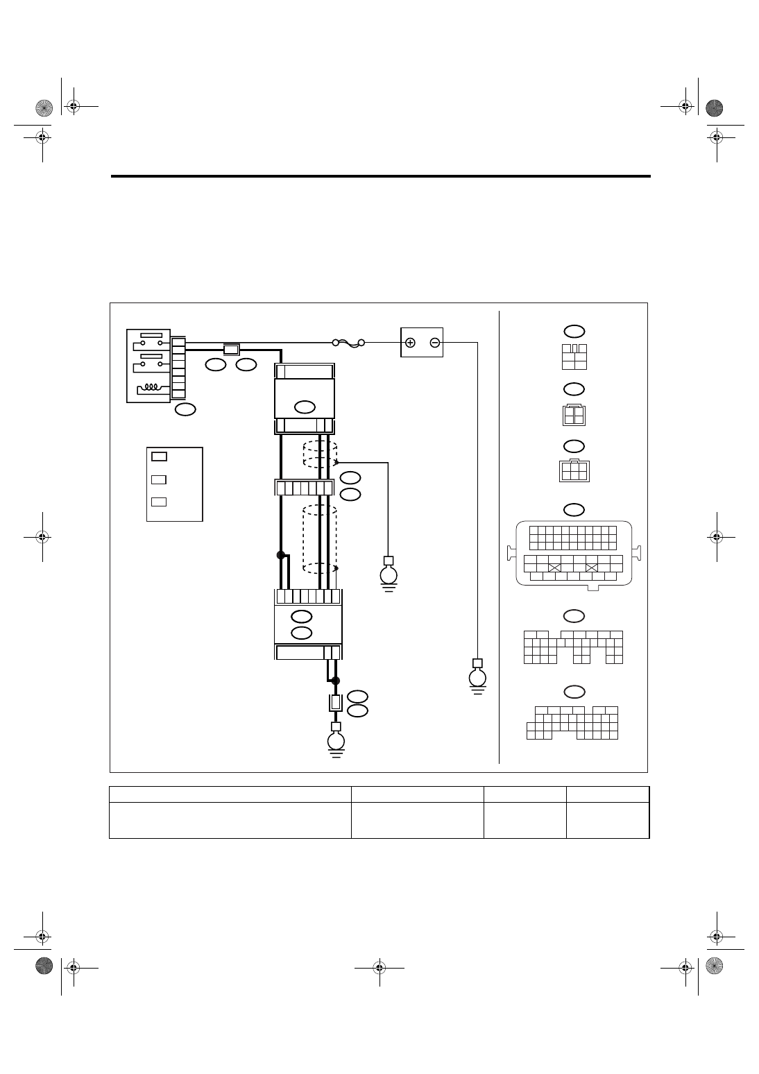
WIRING DIAGRAM:
Step
Check
Yes
No
1
CHECK ANY OTHER DTC ON DISPLAY.
Do DTC P0031 and P0037 dis-
play at the same time on the
Subaru Select Monitor?
EN-03475
3
4
1
2
5
6
B47
SBF-5
E
B47
E24
5
3
4
6
2
1
C34
C35
C33
B3
B2
B1
B135
E
B5
B6
52
B21
E2
B21
E2
50
51
3
4
E2
B21
E
B21
1 2 3 4
12 13 14 15
5 6 7 8
16 17 18 19
9 10 11
20 21 22
23 24 25 26 27 28 29 30 31 32 33
35
34
37
36
39
38
41
40
43
42
44
45
47
46
49
48
51
50
53
52
54
E24
ECM
BATTERY
FRONT OXYGEN
(A/F) SENSOR
MAIN RELAY
B136
B:
C:
1
2
3
4
B135
5
6
7
8
2
1
9
4
3
10
24
22 23
25
11 12 13 14 15
26 27
28
16 17 18 19
20 21
29 30 31
32 33
34 35
B:
B136
5
6
7 8
2
1
9
4
3
10
24
22 23
25
11 12 13 14 15
26 27
28
16
17 18 19 20 21
33 34
29
32
30
31
35
C:
E24
3
2
*
1
*
*
3
LHD : 4
RHD : 1
*
1
*
*
2
3
3
1
6 5 4
2
: RHD
: LHD
LHD : 1
RHD : 4
LHD : 2
RHD : 6

EN(H4SO 2.0)(diag)-72
ENGINE (DIAGNOSTICS)
Diagnostic Procedure with Diagnostic Trouble Code (DTC)
2
CHECK POWER SUPPLY TO FRONT OXY-
GEN (A/F) SENSOR.
1) Turn the ignition switch to OFF.
2) Disconnect the connector from front oxygen
(A/F) sensor.
3) Turn the ignition switch to ON.
4) Measure the voltage between front oxygen
(A/F) sensor connector and engine ground.
Connector & terminal
LHD model
(E24) No. 4 (+) — Engine ground (
−
):
RHD model
(E24) No. 1 (+) — Engine ground (
−
):
Is the voltage more than 10 V? Go to step 3.
Repair the power
supply line.
NOTE:
In this case, repair
the following item:
• Open circuit of
harness between
main relay and
front oxygen (A/F)
sensor connector
• Poor contact in
front oxygen (A/F)
sensor connector
• Poor contact in
main relay connec-
tor
3
CHECK GROUND CIRCUIT FOR ECM.
Measure the resistance of harness between
ECM connector and chassis ground.
Connector & terminal
(B135) No. 5 — Chassis ground:
(B135) No. 6 — Chassis ground:
Is the resistance less than 5
Ω?
Repair the har-
ness and connec-
tor.
NOTE:
In this case, repair
the following item:
• Open circuit of
harness between
ECM and engine
ground terminal
• Poor contact in
ECM connector
• Poor contact in
coupling connector
4
CHECK CURRENT DATA.
1) Start the engine.
2) Read the data of front oxygen (A/F) sensor
heater current using Subaru Select Monitor or
general scan tool.
NOTE:
• Subaru Select Monitor
For detailed operation procedure, refer to
“READ CURRENT DATA FOR ENGINE”. <Ref.
to EN(H4SO 2.0)(diag)-25, Subaru Select
Monitor.>
• General scan tool
For detailed operation procedure, refer to the
general scan tool operation manual.
Is the current more than 0.2 A? Repair the poor
contact in connec-
tor.
NOTE:
In this case, repair
the following item:
• Poor contact in
front oxygen (A/F)
sensor connector
• Poor contact in
ECM connector
5
CHECK INPUT SIGNAL OF ECM.
1) Start and idle the engine.
2) Measure the voltage between ECM con-
nector and chassis ground.
Connector & terminal
(B135) No. 2 (+) — Chassis ground (
−
):
(B135) No. 3 (+) — Chassis ground (
−
):
Is the voltage less than 1 V?
6
CHECK OUTPUT SIGNAL FROM ECM.
Measure the voltage between ECM connector
and chassis ground.
Connector & terminal
(B135) No. 2 (+) — Chassis ground (
−
):
(B135) No. 3 (+) — Chassis ground (
−
):
Does the voltage change by
shaking the ECM harness and
connector while monitoring the
value of voltage meter?
Repair the poor
contact in ECM
connector.
Step
Check
Yes
No
Нет комментариевНе стесняйтесь поделиться с нами вашим ценным мнением.
Текст