Subaru Legacy (2005 year). Service manual — part 118
EN(H4SO 2.0)(diag)-61
ENGINE (DIAGNOSTICS)
Diagnostics for Engine Starting Failure
7
CHECK HARNESS BETWEEN ECM AND
FUEL PUMP RELAY CONNECTOR.
1) Disconnect the connector from ECM.
2) Measure the resistance of harness
between ECM and fuel pump relay connector.
Connector & terminal
RHD model and LHD model (with immo-
bilizer)
(B135) No. 17 — (B362) No. 3:
LHD model (without immobilizer)
(B134) No. 18 — (B362) No. 3:
Is the resistance less than 1
Ω?
Repair the open
circuit of harness
between ECM and
fuel pump relay
connector.
8
CHECK POOR CONTACT.
Check poor contact in ECM connector.
Is there poor contact in ECM
connector?
Repair the poor
contact in ECM
connector.
Check the fuel
injector circuit.
<Ref. to EN(H4SO
2.0)(diag)-62,
FUEL INJECTOR
CIRCUIT, Diag-
nostics for Engine
Starting Failure.>
Step
Check
Yes
No
EN(H4SO 2.0)(diag)-62
ENGINE (DIAGNOSTICS)
Diagnostics for Engine Starting Failure
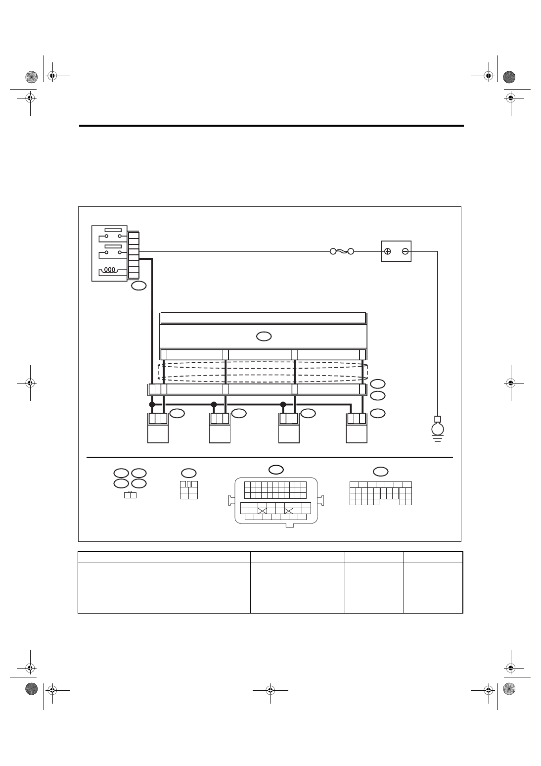
F: FUEL INJECTOR CIRCUIT
CAUTION:
• Check or repair only faulty parts.
• After repair or replacement of faulty parts, perform Clear Memory Mode <Ref. to EN(H4SO 2.0)(di-
ag)-38, OPERATION, Clear Memory Mode.> and Inspection Mode <Ref. to EN(H4SO 2.0)(diag)-32,
PROCEDURE, Inspection Mode.>.
WIRING DIAGRAM:
Step
Check
Yes
No
1
CHECK OPERATION OF EACH FUEL INJEC-
TOR.
While cranking the engine, check each fuel
injector emits operating sound. Use a sound
scope or attach a screwdriver to the injector for
this check.
Does the fuel pump emit oper-
ating sound?
Check the fuel
pressure. <Ref. to
ME(H4SO 2.0)-27,
INSPECTION,
Fuel Pressure.>
EN-03474
E6
E17
E5
E16
1 2
1
2
1
2
1
2
1
2
34
27
17
33
42
48
43
44
45
ECM
B134
E5
E16
E6
E17
B21
E2
FUEL INJECTOR
No. 1
FUEL INJECTOR
No. 2
FUEL INJECTOR
No. 3
FUEL INJECTOR
No. 4
BATTERY
SBF-7
B47
MAIN RELAY
1
2
4
6
3
5
B47
3
4
1
2
5
6
E
B21
1 2 3 4
12 13 14 15
5 6 7 8
16 17 18 19
9 10 11
20 21 22
23 24 25 26 27 28 29 30 31 32 33
35
34
37
36
39
38
41
40
43
42
44
45
47
46
49
48
51
50
53
52
54
B134
5
6
7
8
2
1
9
4
3
10
24
22 23
25
11 12 13 14 15
26 27
28
16 17
18 19 20 21
33 34
29
32
30 31
EN(H4SO 2.0)(diag)-63
ENGINE (DIAGNOSTICS)
Diagnostics for Engine Starting Failure
2
CHECK POWER SUPPLY TO EACH FUEL
INJECTOR.
1) Turn the ignition switch to OFF.
2) Disconnect the connector from fuel injector.
3) Turn the ignition switch to ON.
4) Measure the power supply voltage between
fuel injector terminal and engine ground.
Connector & terminal
#1 (E5) No. 2 (+) — Engine ground (
−
):
#2 (E16) No. 2 (+) — Engine ground (
−
):
#3 (E6) No. 2 (+) — Engine ground (
−
):
#4 (E17) No. 2 (+) — Engine ground (
−
):
Is the voltage more than 10 V? Go to step 3.
Repair the har-
ness and connec-
tor.
NOTE:
In this case, repair
the following item:
• Open circuit of
harness between
main relay and fuel
injector connector
• Poor contact in
main relay connec-
tor
• Poor contact in
coupling connector
• Poor contact in
fuel injector con-
nector
3
CHECK HARNESS BETWEEN ECM AND
FUEL INJECTOR CONNECTOR.
1) Disconnect the connector from ECM.
2) Measure the resistance of harness
between ECM and fuel injector connector.
Connector & terminal
#1 (B134) No. 17 — (E5) No. 1:
#2 (B134) No. 27 — (E16) No. 1:
#3 (B134) No. 34 — (E6) No. 1:
#4 (B134) No. 33 — (E17) No. 1:
Is the resistance less than 1
Ω?
Repair the har-
ness and connec-
tor.
NOTE:
In this case, repair
the following item:
• Open circuit of
harness between
ECM and fuel
injector connector
• Poor contact in
coupling connector
4
CHECK HARNESS BETWEEN ECM AND
FUEL INJECTOR CONNECTOR.
Measure the resistance of harness between
ECM and fuel injector connector.
Connector & terminal
#1 (B134) No. 17 — Chassis ground:
#2 (B134) No. 27 — Chassis ground:
#3 (B134) No. 34 — Chassis ground:
#4 (B134) No. 33 — Chassis ground:
Is the resistance more than 1
M
Ω?
Repair the ground
short circuit of har-
ness between
ECM and fuel
injector connector.
5
CHECK EACH FUEL INJECTOR.
1) Turn the ignition switch to OFF.
2) Measure the resistance between each fuel
injector terminals.
Terminals
No. 1 — No. 2:
Is the resistance 5 — 20
Ω?
Replace the faulty
fuel injector.
6
CHECK POOR CONTACT.
Check poor contact in ECM connector.
Is there poor contact in ECM
connector?
Repair the poor
contact in ECM
connector.
Inspection using
“General Diagnos-
tic Table”. <Ref. to
EN(H4SO
2.0)(diag)-224,
INSPECTION,
General Diagnos-
tic Table.>
Step
Check
Yes
No
EN(H4SO 2.0)(diag)-64
ENGINE (DIAGNOSTICS)
List of Diagnostic Trouble Code (DTC)
17.List of Diagnostic Trouble Code (DTC)
A: LIST
DTC
Item
NOTE
P0030
HO2S Heater Control Circuit (Bank 1
Sensor 1)
P0031
HO2S Heater Control Circuit Low
(Bank 1 Sensor 1)
P0032
HO2S Heater Control Circuit High
(Bank 1 Sensor 1)
P0037
HO2S Heater Control Circuit Low
(Bank 1 Sensor 2)
P0038
HO2S Heater Control Circuit High
(Bank 1 Sensor 2)
P0107
Manifold Absolute Pressure/Baro-
metric Pressure Circuit Low Input
P0108
Manifold Absolute Pressure/Baro-
metric Pressure Circuit High Input
P0112
Intake Air Temperature Sensor 1 Cir-
cuit Low
P0113
Intake Air Temperature Sensor 1 Cir-
cuit High
P0117
Engine Coolant Temperature Circuit
Low
P0118
Engine Coolant Temperature Circuit
High
P0122
Throttle/Pedal Position Sensor/
Switch “A” Circuit Low
P0123
Throttle/Pedal Position Sensor/
Switch “A” Circuit High
P0125
Insufficient Coolant Temperature for
Closed Loop Fuel Control
P0130
O2 Sensor Circuit (Bank1 Sensor1)
P0131
O2 Sensor Circuit Low Voltage (Bank
1 Sensor 1)
P0132
O2 Sensor Circuit High Voltage
(Bank 1 Sensor 1)
P0133
O2 Sensor Circuit Slow Response
(Bank 1 Sensor 1)
Нет комментариевНе стесняйтесь поделиться с нами вашим ценным мнением.
Текст