Subaru Legacy (2005 year). Service manual — part 233

EN(H4SO 2.5)(diag)-217
ENGINE (DIAGNOSTICS)
Diagnostic Procedure with Diagnostic Trouble Code (DTC)
BY:DTC P2017 INTAKE MANIFOLD RUNNER POSITION SENSOR / SWITCH
CIRCUIT HIGH (BANK 1)
DTC DETECTING CONDITION:
Immediately at fault recognition
TROUBLE SYMPTOM:
• Erroneous idling
• Engine stalls.
• Poor driving performance
CAUTION:
After repair or replacement of faulty parts, conduct Clear Memory Mode <Ref. to EN(H4SO 2.5)(diag)-
40, Clear Memory Mode.> and Inspection Mode <Ref. to EN(H4SO 2.5)(diag)-33, Inspection Mode.>.
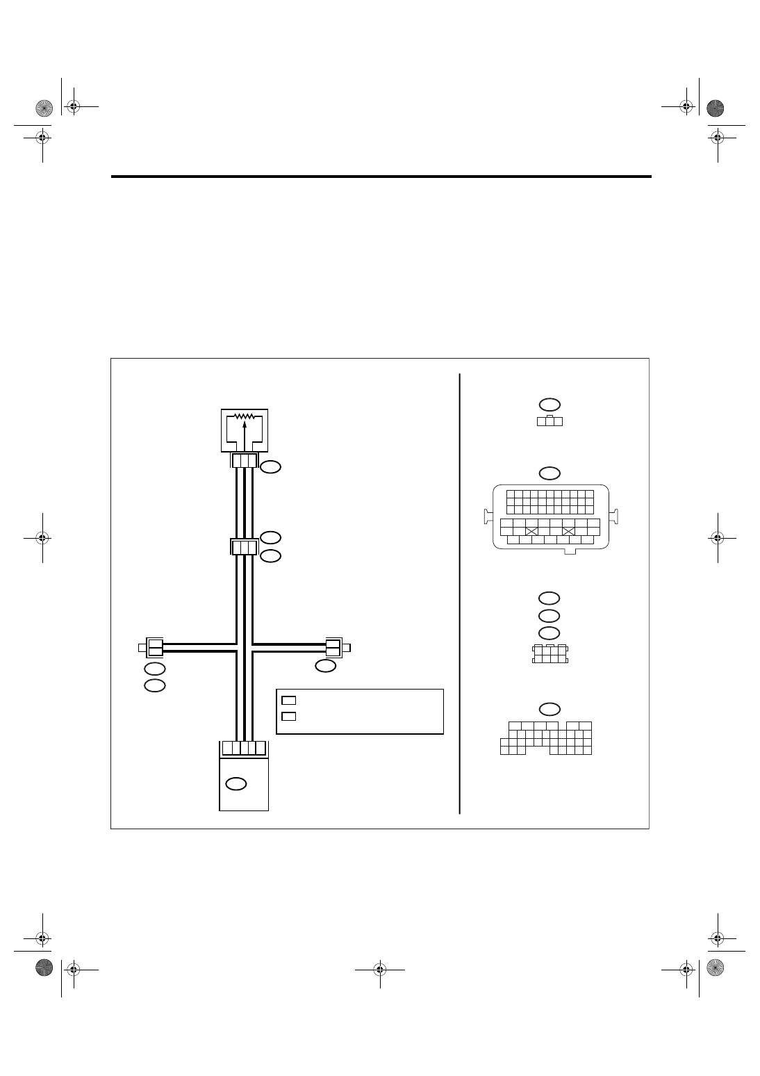
WIRING DIAGRAM:
EN-03467
E2
E54
B21
TUMBLE GENERATOR VALVE
POSITION SENSOR RH
B136 ECM
B136
E54
1 2 3
B21
B138
B122
B83
1 2 3 4
5 6 7 8
5
6
7 8
2
1
9
4
3
10
24
22 23
25
11 12 13 14 15
26 27
28
16
17 18 19 20 21
33 34
29
32
30
31
35
1 2 3 4
12 13 14 15
5 6 7 8
16 17 18 19
9 10 11
20 21 22
23 24 25 26 27 28 29 30 31 32 33
35
34
37
36
39
38
41
40
43
42
44
45
47
46
49
48
51
50
53
52
54
E2
B21
B83
B122 : RHD
B138 : LHD
20
10
19
16
35
27
1
3
2
*
: TERMINAL No. RANDOM ARRANGEMENT
1
*
: TERMINAL No. RANDOM ARRANGEMENT
AMONG 1,2,5, AND 6
2
2
2
*
*
*
*
1
1
EN(H4SO 2.5)(diag)-218
ENGINE (DIAGNOSTICS)
Diagnostic Procedure with Diagnostic Trouble Code (DTC)
Step
Check
Yes
No
1
CHECK CURRENT DATA.
1) Start the engine.
2) Read the data of tumble generator valve
position sensor signal using Subaru Select
Monitor or general scan tool.
NOTE:
• Subaru Select Monitor
For detailed operation procedure, refer to
“READ CURRENT DATA FOR ENGINE”. <Ref.
to EN(H4SO 2.5)(diag)-25, Subaru Select
Monitor.>
• General scan tool
For detailed operation procedure, refer to the
general scan tool operation manual.
Is the voltage more than 4.9 V? Go to step 2.
Even if the mal-
function indicator
light illuminates,
the circuit has
returned to a nor-
mal condition at
this time. A tempo-
rary poor contact
of the connector
may be the cause.
NOTE:
In this case, repair
the following:
• Poor contact in
tumble generator
valve position sen-
sor connector
• Poor contact in
ECM connector
• Poor contact in
coupling connector
2
CHECK HARNESS BETWEEN TUMBLE
GENERATOR VALVE POSITION SENSOR
CONNECTOR AND ECM CONNECTOR.
1) Turn the ignition switch to OFF.
2) Disconnect the connector from tumble gen-
erator valve position sensor.
3) Measure the resistance of harness
between tumble generator valve position sen-
sor connector and engine ground.
Connector & terminal
(E54) No. 2 — Engine ground:
Is the resistance less than 5
Ω?
Repair the har-
ness and connec-
tor.
NOTE:
In this case, repair
the following:
• Open circuit of
harness between
tumble generator
valve position sen-
sor and ECM con-
nector
• Poor contact in
coupling connector
• Poor contact in
joint connector
3
CHECK HARNESS BETWEEN TUMBLE
GENERATOR VALVE POSITION SENSOR
CONNECTOR AND ECM CONNECTOR.
1) Turn the ignition switch to ON.
2) Measure the voltage between tumble gen-
erator valve position sensor connector and
engine ground.
Connector & terminal
(E54) No. 3 (+) — Engine ground (
−
):
Is the voltage more than 4.9 V? Repair the battery
short circuit of har-
ness between tum-
ble generator valve
position sensor
and ECM connec-
tor. After repair,
replace the ECM.
<Ref. to FU(H4SO
2.5)-37, Engine
Control Module
(ECM).>
Replace the tum-
ble generator valve
position sensor.
<Ref. to FU(H4SO
2.5)-30, Tumble
Generator Valve
Position Sensor.>
EN(H4SO 2.5)(diag)-219
ENGINE (DIAGNOSTICS)
Diagnostic Procedure with Diagnostic Trouble Code (DTC)
BZ:DTC P2021 INTAKE MANIFOLD RUNNER POSITION SENSOR / SWITCH CIR-
CUIT LOW (BANK 2)
DTC DETECTING CONDITION:
Immediately at fault recognition
TROUBLE SYMPTOM:
• Erroneous idling
• Engine stalls.
• Poor driving performance
CAUTION:
After repair or replacement of faulty parts, conduct Clear Memory Mode <Ref. to EN(H4SO 2.5)(diag)-
40, Clear Memory Mode.> and Inspection Mode <Ref. to EN(H4SO 2.5)(diag)-33, Inspection Mode.>.
WIRING DIAGRAM:
EN-03466
E2
E50
B21
B136 ECM
TUMBLE GENERATOR VALVE
POSITION SENSOR LH
B83
2
2
B122 : RHD
B138 : LHD
16
35
26
20
11
19
1
3
2
B136
E50
1 2 3
B21
B138
B122
B83
1 2 3 4
5 6 7 8
5
6
7 8
2
1
9
4
3
10
24
22 23
25
11 12 13 14 15
26 27
28
16
17 18 19 20 21
33 34
29
32
30
31
35
1 2 3 4
12 13 14 15
5 6 7 8
16 17 18 19
9 10 11
20 21 22
23 24 25 26 27 28 29 30 31 32 33
35
34
37
36
39
38
41
40
43
42
44
45
47
46
49
48
51
50
53
52
54
*
*
*
*
1
1
*
: TERMINAL No. RANDOM ARRANGEMENT
1
*
: TERMINAL No. RANDOM ARRANGEMENT
AMONG 1,2,5, AND 6
2

EN(H4SO 2.5)(diag)-220
ENGINE (DIAGNOSTICS)
Diagnostic Procedure with Diagnostic Trouble Code (DTC)
Step
Check
Yes
No
1
CHECK CURRENT DATA.
1) Start the engine.
2) Read the data of tumble generator valve
position sensor signal using Subaru Select
Monitor or general scan tool.
NOTE:
• Subaru Select Monitor
For detailed operation procedure, refer to
“READ CURRENT DATA FOR ENGINE”. <Ref.
to EN(H4SO 2.5)(diag)-25, Subaru Select
Monitor.>
• General scan tool
For detailed operation procedure, refer to the
general scan tool operation manual.
Is the voltage less than 0.1 V? Go to step 2.
Even if the mal-
function indicator
light illuminates,
the circuit has
returned to a nor-
mal condition at
this time. A tempo-
rary poor contact
of the connector
may be the cause.
NOTE:
In this case, repair
the following:
• Poor contact in
tumble generator
valve position sen-
sor connector
• Poor contact in
ECM connector
• Poor contact in
coupling connector
2
CHECK INPUT SIGNAL OF ECM.
Measure the voltage between ECM connector
and chassis ground.
Connector & terminal
(B136) No. 16 (+) — Chassis ground (
−
):
Is the voltage more than 4.5 V? Go to step 4.
3
CHECK INPUT SIGNAL OF ECM.
Measure the voltage between ECM connector
and chassis ground.
Connector & terminal
(B136) No. 16 (+) — Chassis ground (
−
):
Does the voltage change by
shaking the harness and con-
nector of ECM while monitor-
ing the value with voltage
meter?
Repair the poor
contact in ECM
connector.
Contact the SUB-
ARU dealer.
4
CHECK INPUT SIGNAL OF ECM.
Measure the voltage between ECM connector
and chassis ground.
Connector & terminal
(B136) No. 26 (+) — Chassis ground (
−
):
Is the voltage less than 0.1 V? Go to step 6.
5
CHECK INPUT SIGNAL OF ECM (USING
SUBARU SELECT MONITOR).
Measure the voltage between ECM connector
and chassis ground.
Does the voltage change by
shaking the harness and con-
nector of ECM while monitor-
ing the value with Subaru
Select Monitor?
Repair the poor
contact in ECM
connector.
Нет комментариевНе стесняйтесь поделиться с нами вашим ценным мнением.
Текст