Subaru Legacy (2005 year). Service manual — part 1014
CC-3
CRUISE CONTROL SYSTEM
General Description
B: CAUTION
• Before disassembling or reassembling parts, al-
ways disconnect the battery ground cable from bat-
tery. When repairing the audio, control module, etc.
which are provided with memory functions, record
the memory contents before disconnecting the
ground cable from battery. Otherwise, the memory
will be erased.
• Reassemble the parts in the reverse order of dis-
assembly unless otherwise indicated.
• Adjust the parts to specifications specified in this
manual.
• Connect the connectors securely during reas-
sembly.
• After reassembly, ensure functional parts oper-
ate properly.
C: PREPARATION TOOL
TOOL NAME
REMARKS
Circuit tester
Used for measuring resis-
tance and voltage.
TORX
®
BIT T30
Used for removing and
installing driver’s airbag
module.
CC-4
CRUISE CONTROL SYSTEM
Cruise Control Unit
2. Cruise Control Unit
A: NOTE
The control of cruise control system is carried out in
Engine control module (ECM).
B: REMOVAL
C: INSTALLATION
CC-5
CRUISE CONTROL SYSTEM
Cruise Control Command Switch
3. Cruise Control Command
Switch
A: REMOVAL
WARNING:
Before servicing, be sure to read the notes in
the “AB” section for proper handling of the
driver’s airbag module. <Ref. to AB-5, CAU-
TION, General Description.>
1) Set the front wheels in straight ahead position.
2) Turn the ignition switch to OFF.
3) Disconnect the ground cable from battery and
wait for at least 20 seconds before starting work.
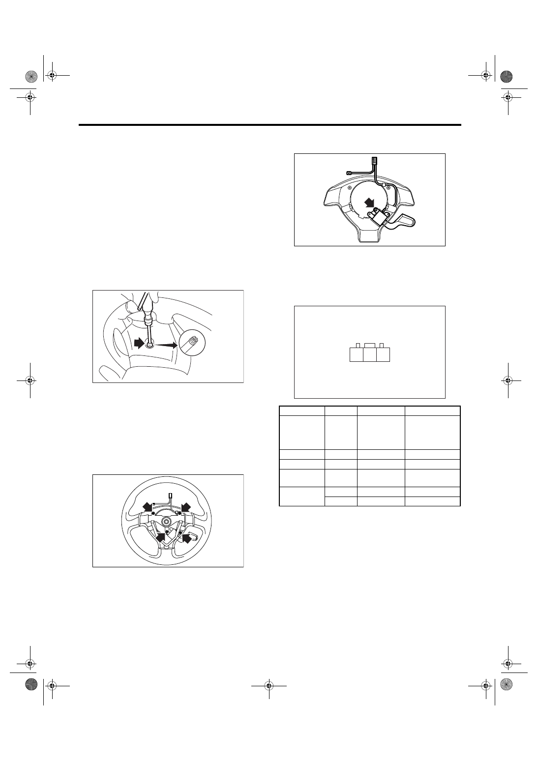
4) Using TORX
®
BIT T30 (Tamper resistant type),
loosen the two TORX
®
bolts which secure driver’s
airbag module.
5) Disconnect the airbag module connector on
back of the airbag module. <Ref. to AB-11, PRO-
CEDURE, Airbag Connector.>
6) Remove the steering wheel. <Ref. to PS-21, RE-
MOVAL, Steering Wheel.>
7) Remove the four screws to remove the lower
cover from steering wheel.
8) Remove one screw to remove the cruise control
command switch from lower cover.
B: INSTALLATION
Install in the reverse order of removal.
C: INSPECTION
Measure the cruise control command switch resis-
tance.
If NG, replace the cruise control command switch.
(1) TORX
®
BIT T30
CC-00018
(1)
CC-00181
Switch
Area
Terminal No.
Standard
CANCEL
SET/COAST
RESUME/
ACCEL
ALL
OFF
2 and 3
Approx. 4 k
Ω
CANCEL
ON
2 and 3
Less than 1
Ω
SET/COAST
ON
2 and 3
Approx. 250
Ω
RESUME/
ACCEL
ON
2 and 3
Approx. 1500
Ω
MAIN
OFF
1 and 2
More than 1 M
Ω
ON
1 and 2
Less than 1
Ω
CC-00182
CC-00252
2 3
1
CC-6
CRUISE CONTROL SYSTEM
Stop Light & Brake Switch
4. Stop Light & Brake Switch
A: REMOVAL
1) Disconnect the ground cable from battery.
2) Disconnect the connector from stop light & brake
switch, and then remove the switch. <Ref. to BR-
45, REMOVAL, Stop Light Switch.>
B: INSTALLATION
Install in the reverse order of removal.
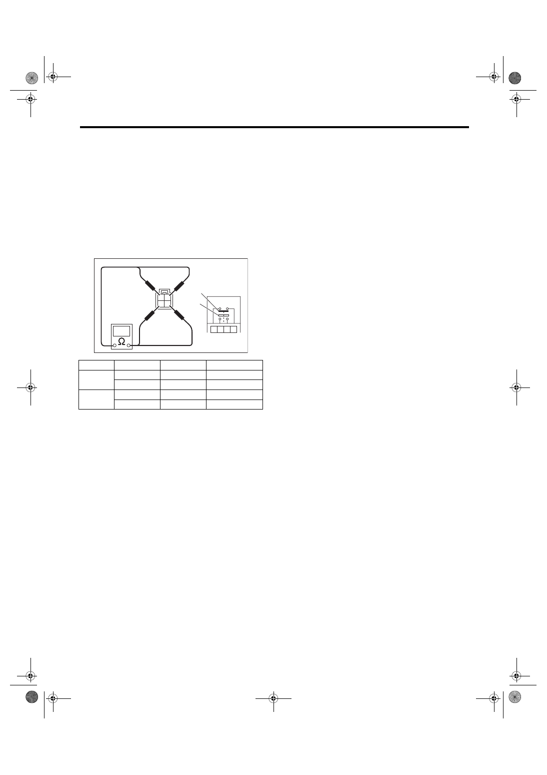
C: INSPECTION
Measure the resistance of brake switch (A) and
stop light switch (B).
If NG, replace the stop light & brake switch.
Switch
Pedal
Terminal No.
Standard
Brake
Released
1 and 4
Less than 1
Ω
Depressed
1 and 4
More than 1 M
Ω
Stop
Light
Released
2 and 3
More than 1 M
Ω
Depressed
2 and 3
Less than 1
Ω
CC-00022
1
2
3
4
(A)
(B)
3
2
1
4
Нет комментариевНе стесняйтесь поделиться с нами вашим ценным мнением.
Текст