Subaru Legacy (2005 year). Service manual — part 885
AB-15
AIRBAG SYSTEM
Inspection Locations After a Collision
5. AIRBAG CONTROL MODULE
Perform the inspection of the following items, and
replace the damaged parts with new ones.
• Control module is cracked or deformed.
• Mounting bracket is cracked or deformed.
• Connector is scratched, cracked or deformed.
• Airbag is deployed.
• Side airbag is deployed.
• Curtain airbag is deployed.
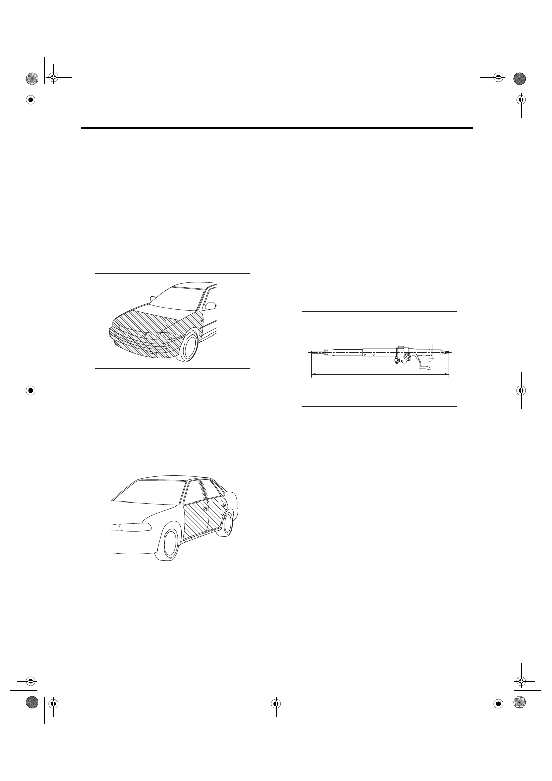
6. FRONT SUB SENSOR
If the section of vehicle as shown in the figure is
damaged, check the following items and replace
the damaged parts with new parts.
• Front sub sensor is cracked or deformed.
• Mounting bracket is cracked or deformed.
• Connector is scratched, cracked or deformed.
• Airbag is deployed.
7. SIDE AIRBAG SENSOR AND CURTAIN
AIRBAG SENSOR
If the section of vehicle as shown in the figure is
damaged, check the following items and replace
the damaged parts with new parts.
• Side airbag sensor and curtain airbag sensor are
cracked or deformed.
• Mounting bracket is cracked or deformed.
• Connector is scratched, cracked or deformed.
• Side airbag sensor or curtain airbag is deployed.
(operating side)
8. ROLL CONNECTOR
Perform the inspection of the following items, and
replace the damaged parts with new ones.
• Combination switch or steering roll connector is
cracked or deformed.
9. STEERING SHAFT
Perform the inspection of the following items, and
replace the damaged parts with new ones.
• Overall length of steering column should be with-
in specification.
Specification:
Overall length L
Except for OUTBACK model
833.6
+1.3
−0.3
mm (32.82
+0.051
−0.012
in)
OUTBACK model
825.4
+1.3
−0.3
mm (32.50
+0.051
−0.012
in)
AB-00029
AB-00030
AB-00728
L
AB-16
AIRBAG SYSTEM
Driver’s Airbag Module
4. Driver’s Airbag Module
A: REMOVAL
CAUTION:
Refer to “CAUTION” of General Description be-
fore handling the airbag module. <Ref. to AB-5,
CAUTION, General Description.>
1) Position the front wheels straight ahead. (After
moving a vehicle more than 5 m (16 ft) with front
wheels positioned straight ahead, make sure that
the vehicle moves straight ahead).)
2) Turn the ignition switch to OFF.
3) Disconnect the ground cable from battery and
wait for at least 20 seconds before starting work.
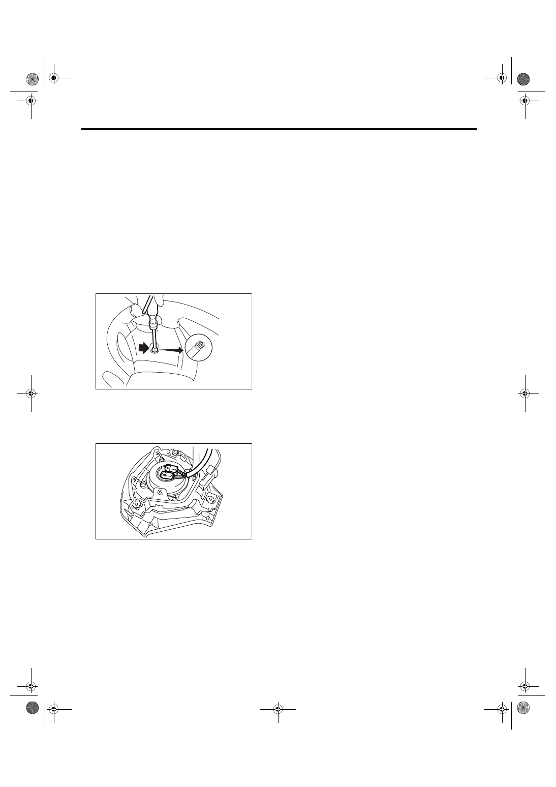
4) Using TORX
®
BIT T30 (1), remove the two
TORX
®
bolts on the side of steering wheel.
5) Disconnect the horn harness.
6) Disconnect the airbag connector on the back of
airbag module, and then remove the airbag mod-
ule. <Ref. to AB-11, PROCEDURE, Airbag Con-
nector.>
7) Refer to the “CAUTION” for handling of a re-
moved airbag module. <Ref. to AB-5, CAUTION,
General Description.>
B: INSTALLATION
CAUTION:
• Refer to “CAUTION” of General Description
before handling the airbag module. <Ref. to AB-
5, CAUTION, General Description.>
• Do not allow harness and connectors to inter-
fere or get tangled up with other parts.
• To prevent the misconnection, the connector
is colored. Connect the harness side connector
to the same color of module side connector.
Install in the reverse order of removal.
Tightening torque:
10 N
⋅
m (1.0 kgf-m, 7.2 ft-lb)
C: INSPECTION
CAUTION:
Refer to “CAUTION” of General Description be-
fore handling the airbag module. <Ref. to AB-5,
CAUTION, General Description.>
Perform the inspection of the following items, and
replace the damaged parts with new ones.
• Airbag module, harness, connector and mount-
ing bracket are damaged. <Ref. to AB-14, DRIV-
ER’S AIRBAG MODULE, INSPECTION,
Inspection Locations After a Collision.>
CC-00018
(1)
AB-00622
AB-17
AIRBAG SYSTEM
Passenger’s Airbag Module
5. Passenger’s Airbag Module
A: REMOVAL
CAUTION:
Refer to “CAUTION” of General Description be-
fore handling the airbag module. <Ref. to AB-5,
CAUTION, General Description.>
1) Turn the ignition switch to OFF.
2) Disconnect the ground cable from battery and
wait for at least 20 seconds before starting work.
3) Remove the instrument panel. <Ref. to EI-56,
INSTRUMENT PANEL (EXCLUDING STEERING
SUPPORT BEAM), REMOVAL, Instrument Panel
Assembly.>
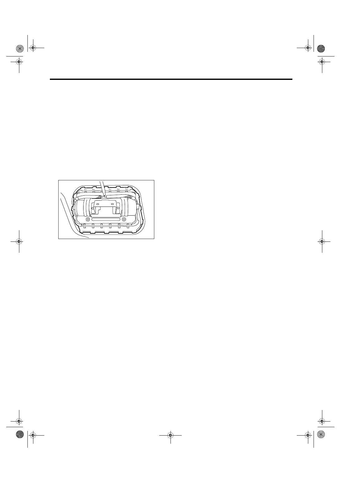
4) Remove the pawl, and remove the passenger’s
airbag module.
5) Refer to the “CAUTION” for handling of a re-
moved airbag module. <Ref. to AB-5, CAUTION,
General Description.>
B: INSTALLATION
CAUTION:
Refer to “CAUTION” of General Description be-
fore handling the airbag module. <Ref. to AB-5,
CAUTION, General Description.>
Install in the reverse order of removal.
CAUTION:
Do not allow harness and connectors to inter-
fere or get tangled up with other parts.
Tightening torque:
7.4 N
⋅
m (0.75 kgf-m, 5.5 ft-lb)
C: INSPECTION
CAUTION:
Refer to “CAUTION” of General Description be-
fore handling the airbag module. <Ref. to AB-5,
CAUTION, General Description.>
Perform the inspection of the following items, and
replace the damaged parts with new ones.
• Airbag module, harness, connector and mount-
ing bracket are damaged. <Ref. to AB-14, PAS-
SENGER’S AIRBAG MODULE, INSPECTION,
Inspection Locations After a Collision.>
EI-00615
AB-18
AIRBAG SYSTEM
Side Airbag Module
6. Side Airbag Module
A: REMOVAL
CAUTION:
Refer to “CAUTION” of General Description be-
fore handling the airbag module. <Ref. to AB-5,
CAUTION, General Description.>
NOTE:
Remove the passenger’s side by referring to driv-
er’s side.
1) Turn the ignition switch to OFF.
2) Disconnect the ground cable from battery and
wait for at least 20 seconds before starting work.
3) Remove the front seats. <Ref. to SE-7, REMOV-
AL, Front Seat.>
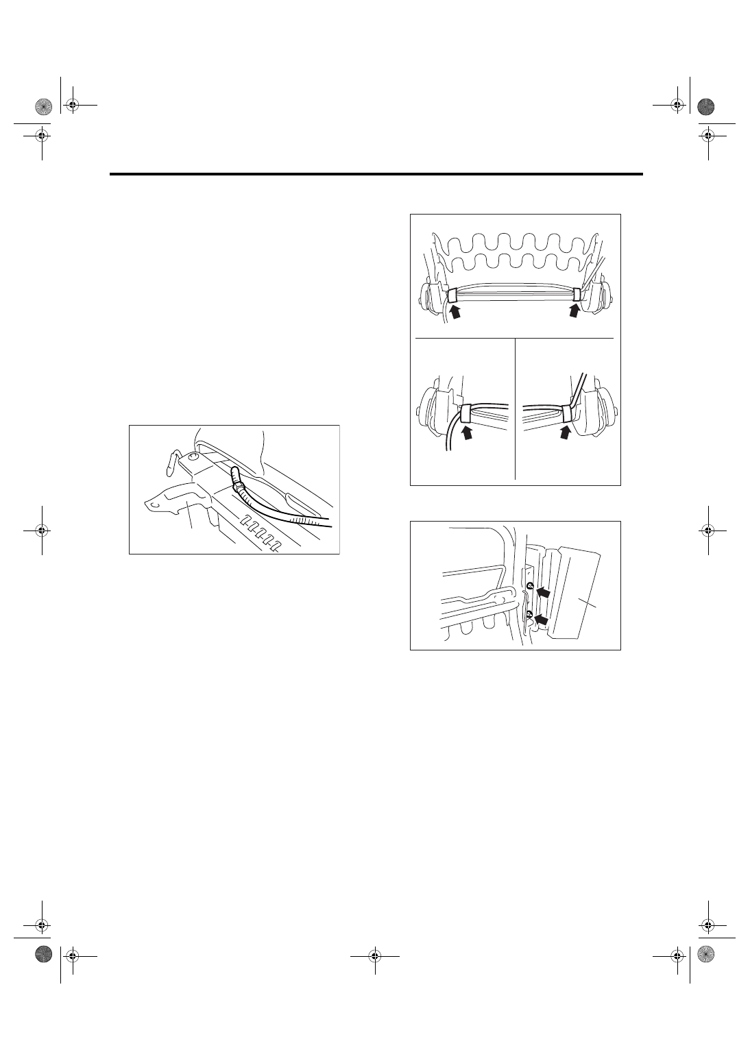
4) Remove the clip from reverse side of seat cush-
ion assembly and inner slide rail (A), and then re-
move the side airbag harness. (Manual seat model)
5) Remove the side airbag harness from back side
of seat cushion assembly. (Power seat model)
6) Remove the backrest cover. <Ref. to SE-7, DIS-
ASSEMBLY, Front Seat.>
7) Remove the side airbag harness from backrest
frame assembly.
8) Remove the side airbag module (A) from back-
rest frame assembly.
AB-00472
(A)
AB-00945
AB-00451
(A)
Нет комментариевНе стесняйтесь поделиться с нами вашим ценным мнением.
Текст