Subaru Legacy (2005 year). Service manual — part 655
5MT-67
MANUAL TRANSMISSION AND DIFFERENTIAL
Main Shaft Assembly for Dual-Range
ST1
499757002
INSTALLER
ST2
498077400
SYNCHRO CONE REMOV-
ER
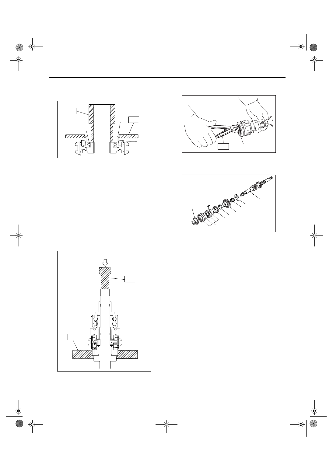
6) Using the ST1 and ST2, remove rest of the
parts.
NOTE:
• When replacing the sleeve and hub with new
ones, replace them as a set.
• Do not disassemble the sleeve and hub, be-
cause the aligning position is specified.
• If it is necessary to disassemble, mark the en-
gaging points on the splines beforehand.
ST1
899864100
REMOVER
ST2
899714110
REMOVER
7) Remove the snap ring from main shaft.
ST
899474100
EXPANDER
8) Remove rest of the parts.
(A) Ball bearing
(B) Synchro cone
(C) Baulk ring
(A) Press
MT-00189
(B)
(A)
(C)
ST2
ST1
MT-00190
(A)
ST2
ST1
(A) Snap ring
(A) Sleeve & hub ASSY
(B) High-low baulk ring
(C) Friction damper
(D) Low input gear
(E) Needle bearing
(F) Input low gear spacer
(G) Ball
MT-00215
( A )
S T
MT-00216
(B)
(A)
(E)
(F)
(G)
(D)
(C)
(B)
5MT-68
MANUAL TRANSMISSION AND DIFFERENTIAL
Main Shaft Assembly for Dual-Range
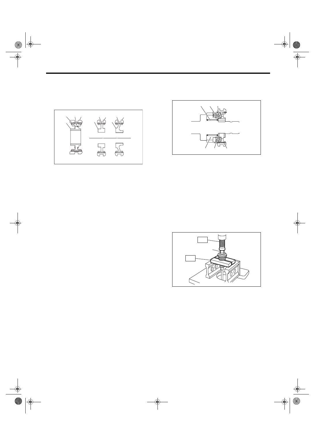
D: ASSEMBLY
1) Assemble with aligning the matching mark if the
sleeve & hub assembly have been disassembled.
NOTE:
Position the open ends of spring 120
° apart.
2) Install the 3rd drive gear, outer baulk ring, syn-
chro cone, inner baulk ring, sleeve & hub assembly
for 3rd needle bearing, on the transmission main
shaft.
NOTE:
Align the groove in baulk ring with shifting insert.
3) Install the 4th needle bearing race onto trans-
mission main shaft using ST1, ST2 and a press.
ST1
899714110
REMOVER
ST2
499877000
RACE 4-5 INSTALLER
(A) High-low coupling sleeve
(B) Shifting insert
(C) High-low synchronizer spring
(D) High-low synchronizer hub
(E) Sleeve
(F) Insert key
(G) 3rd-4th synchronizer hub
(H) Sleeve
(I) Insert key
(J) 5th-Rev synchronizer hub
(K) High side
(L) Low side
(M) 3rd side
(N) 4th side
(O) 5th side
(P) Rev side
MT-00217
( B ) ( A )
( D )
( G )
( F ) ( E )
( I )
( H )
( J )
( K )
( L )
( M ) ( N )
( O ) ( P )
( C )
(A) 3rd needle bearing
(B) 3rd drive gear
(C) Inner baulk ring
(D) Synchro cone
(E) Outer baulk ring
(F) Sleeve & hub ASSY
(A) 4th needle bearing race
MT-01318
(A)
(B)
(C)
(D)
(E)
(F)
MT-00201
(A)
ST1
ST2
5MT-69
MANUAL TRANSMISSION AND DIFFERENTIAL
Main Shaft Assembly for Dual-Range
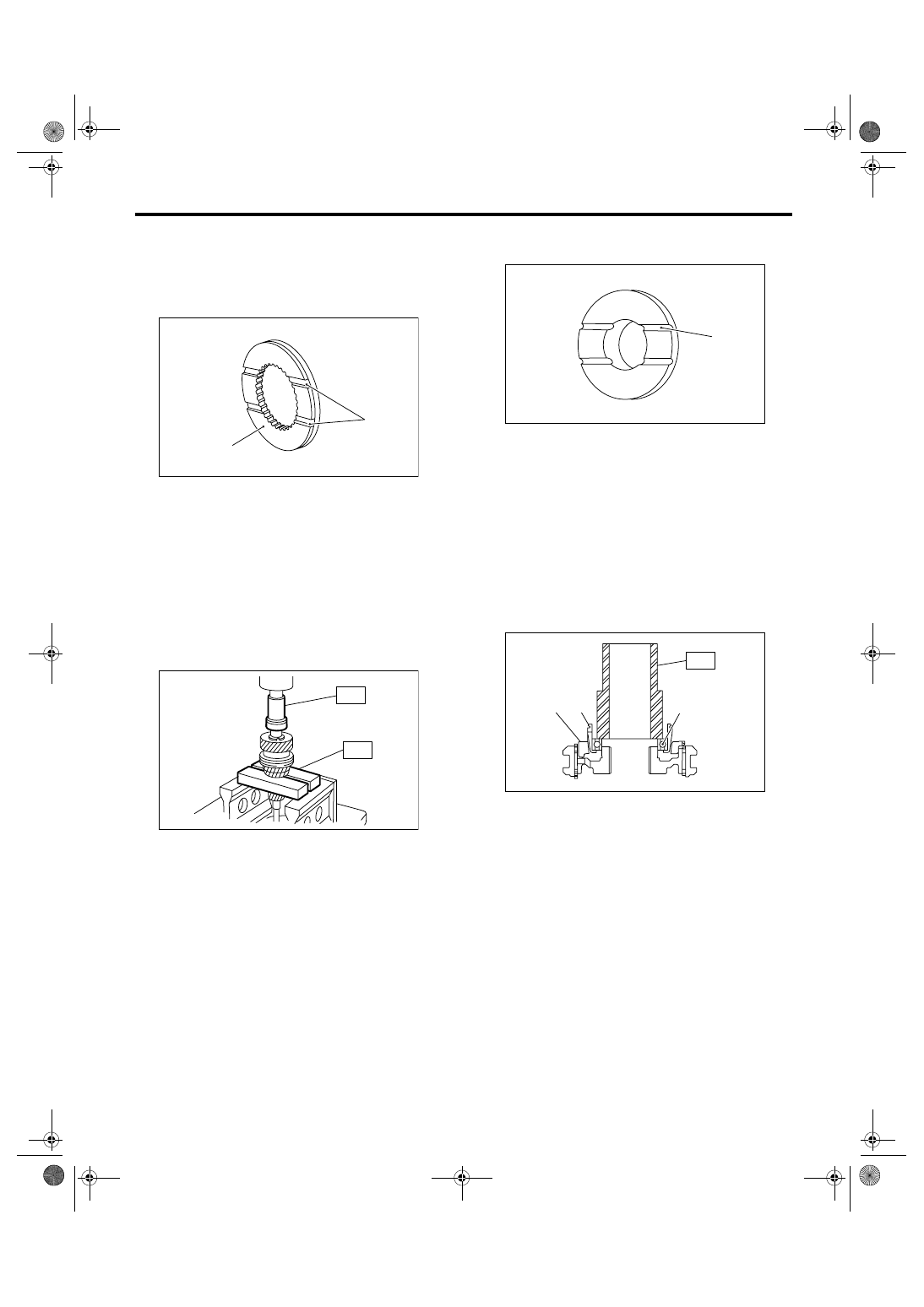
4) Install the baulk ring, needle bearing, 4th drive
gear and 4th gear thrust washer to transmission
main shaft.
NOTE:
Face the thrust washer in correct direction.
5) Press-fit the ball bearing into the rear section of
transmission main shaft using ST1, ST2 and a
press.
NOTE:
Do not apply pressure in excess of 10 kN (1 ton, 1.1
US ton, 1.0 Imp ton).
ST1
899714110
REMOVER
ST2
499877000
RACE 4-5 INSTALLER
6) Using the ST1 and ST2, install the 5th gear
thrust washer and 5th needle bearing race onto the
rear section of transmission main shaft.
NOTE:
• Do not apply pressure in excess of 10 kN (1 ton,
1.1 US ton, 1.0 Imp ton).
• Face the thrust washer in correct direction.
ST1
899714110
REMOVER
ST2
499877000
RACE 4-5 INSTALLER
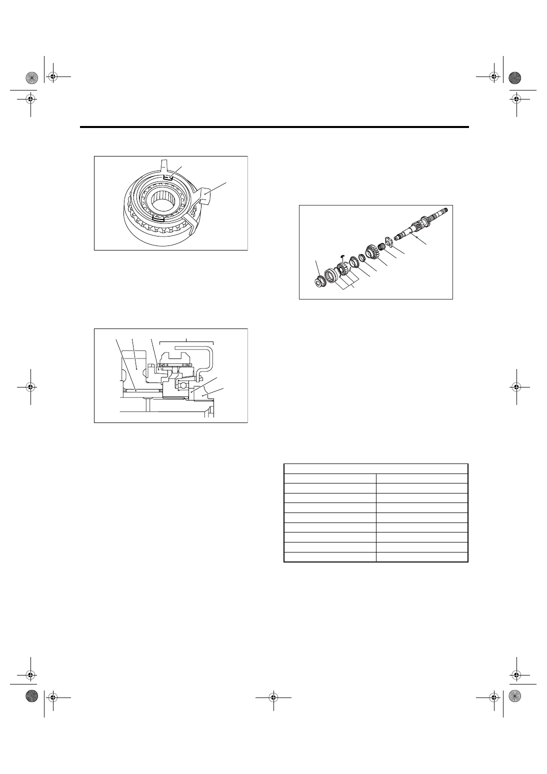
7) Install the bearing onto synchro cone.
8) Install the baulk ring and synchro cone onto 5th-
Rev sleeve & hub assembly using ST and a press.
NOTE:
• Do not apply pressure in excess of 10 kN (1 ton,
1.1 US ton, 1.0 Imp ton).
• Use a new ball bearing.
• After press-fitting, make sure the synchro cone
rotates freely.
ST
499757002
INSTALLER
(A) Groove
(B) 4th gear side
MT-00193
(A)
(B)
MT-00194
ST1
ST2
(A) Face this surface to 5th gear side.
(A) Baulk ring
(B) Synchro cone
(C) Ball bearing
MT-00195
(A)
MT-00196
(B)
(A)
(C)
ST
5MT-70
MANUAL TRANSMISSION AND DIFFERENTIAL
Main Shaft Assembly for Dual-Range
9) Install the synchro cone stopper and snap ring to
5th-Rev sleeve & hub assembly.
10) Install rest of the parts to the rear section of
transmission main shaft.
NOTE:
Align the groove in baulk ring with shifting insert.
11) Tighten the lock nuts to the specified torque us-
ing ST1 and ST2.
NOTE:
Stake the caulking of lock nuts in two places after
tightening.
ST1
499987003
SOCKET WRENCH (35)
ST2
498937000
TRANSMISSION HOLDER
Tightening torque:
120 N
⋅
m (12.2 kgf-m, 88.5 ft-lb)
12) Install the needle bearing on main shaft.
13) Install rest of the parts to the front section of
transmission main shaft.
NOTE:
• Be careful not to damage the graded section of
transmission main shaft when installing the needle
bearing.
• Face the grooved side toward input gear.
• Align the high-low baulk ring’s groove with shift-
ing insert.
14) Install a new snap ring to the rod section of
transmission main shaft using ST1 and ST2.
NOTE:
Select a suitable outer snap ring so that axial clear-
ance between snap ring and hub is held within
0.060 to 0.100 mm (0.0024 to 0.0039 in).
ST1
499757002
INSTALLER
ST2
499757001
SNAP RING GUIDE
(A) Synchro cone stopper
(B) Snap ring
(A) Needle bearing
(B) 5th drive gear
(C) Baulk ring
(D) 5th-Rev sleeve & hub ASSY
(E) Lock washer
(F) Lock nuts
MT-00188
(A)
(B)
MT-00198
(A)
(B)
(C)
(D)
(E)
(F)
(A) Ball
(B) Input low gear spacer
(C) Needle bearing
(D) Input low gear
(E) Friction damper
(F) High-low baulk ring
(G) Sleeve & hub ASSY
Snap ring
Part No.
Thickness mm (in)
805025051
2.42 (0.0953)
805025052
2.47 (0.0972)
805025053
2.52 (0.0992)
805025054
2.57 (0.1012)
805025055
2.62 (0.1031)
805025056
2.67 (0.1051)
805025057
2.72 (0.1071)
805025058
2.37 (0.0933)
MT-00225
(F)
(G)
(C)
(B)
(A)
(D)
(E)
(F)
Нет комментариевНе стесняйтесь поделиться с нами вашим ценным мнением.
Текст