Subaru Legacy (2005 year). Service manual — part 653
5MT-59
MANUAL TRANSMISSION AND DIFFERENTIAL
Transmission Case
Liquid gasket:
THREE BOND (Part No. 004403007) 1215 or
equivalent
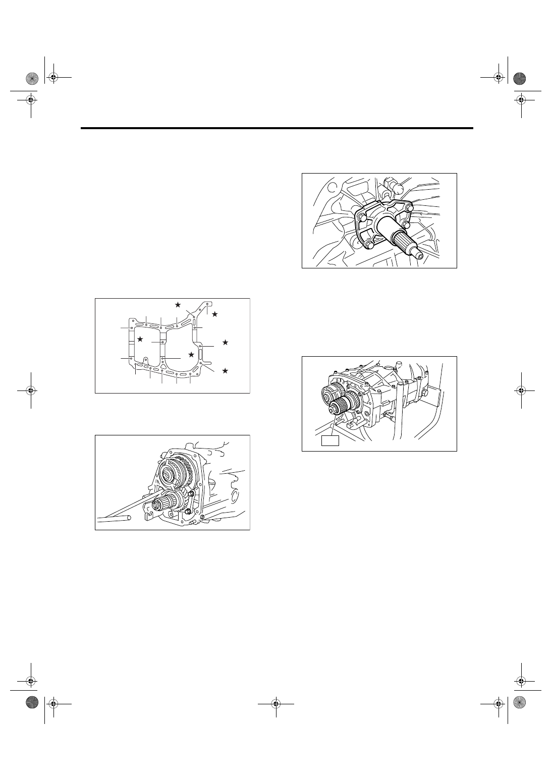
6) Tighten the seventeen bolts with bracket, clip,
etc. as shown in the figure.
NOTE:
• Insert the bolts from the bottom and tighten the
nuts at the top.
• Put the cases together being careful that the
drive pinion shim and input shaft holder shim are
not caught up in between.
Tightening torque:
8 mm bolt
25 N
⋅
m (2.5 kgf-m, 18.4 ft-lb)
★
10 mm bolt
39 N
⋅
m (4.0 kgf-m, 28.9 ft-lb)
7) Tighten the ball bearing mounting bolts.
Tightening torque:
30 N
⋅
m (3.1 kgf-m, 22.4 ft-lb)
8) Tighten the input shaft holder attaching bolts.
Tightening torque:
20 N
⋅
m (2.0 kgf-m, 14.5 ft-lb)
9) Backlash adjustment of hypoid gear and preload
adjustment of roller bearing
NOTE:
Set the ST to drive pinion assembly.
ST
498427100
STOPPER
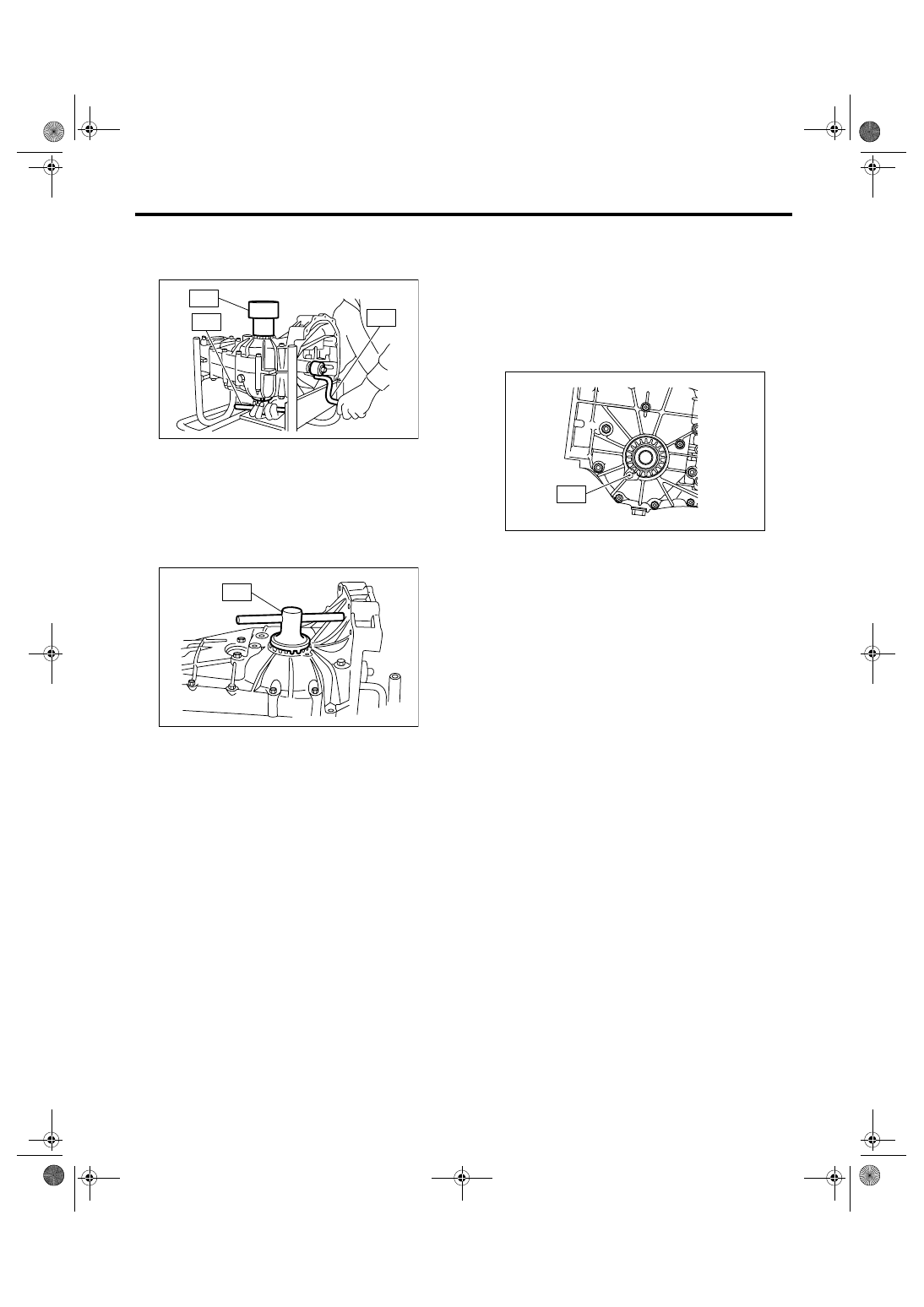
10) Place the transmission with the left side of case
facing downward, and put ST1 on bearing cup.
11) Screw the retainer assembly into left case from
the bottom using ST2. Fit the ST3 on transmission
main shaft. Shift the gear into 4th or 5th and turn
the shaft several times. Screw in the retainer while
turning ST3 until a slight resistance is felt on ST2.
This is the contact point of hypoid gear and drive
pinion shaft. Repeat the above sequence several
times to ensure the contact point.
MT-00178
(9)
(7)
(5)
(16)
(17)
(11)
(3)
(4)
(2)
(1)
(12)
(8)
(6)
(10)
(14)
(15)
(13)
MT-00158
(A) Input shaft holder
(B) Input shaft
MT-00163
(A)
(B)
MT-00174
ST
5MT-60
MANUAL TRANSMISSION AND DIFFERENTIAL
Transmission Case
ST1
399780104
WEIGHT
ST2
499787000
WRENCH ASSY
ST3
499927100
HANDLE
12) Remove the weight, and screw in the retainer
without O-ring on upper side and stop at the point
where slight resistance is felt.
NOTE:
In this condition, the backlash between hypoid gear
and drive pinion shaft is zero.
ST
499787000
WRENCH ASSY
13) Loosen the retainer on the lower side by 3
notches and turn in the retainer on upper side by
the same amount in order to obtain the backlash.
14) Turn in the retainer on the upper side addition-
ally by 1 notch in order to apply preload on taper
roller bearing.
15) Install temporarily both the upper and lower
lock plates and mark both holder and lock plate for
later readjustment.
NOTE:
Install the lock plate upside down if it is hard to in-
stall.
16) Turn the transmission main shaft several times
while tapping around the retainer lightly with plastic
hammer.
17) Inspect and adjust the backlash and tooth con-
tact of hypoid gear. <Ref. to 5MT-87, INSPEC-
TION, Front Differential Assembly.>
18) After checking the tooth contact of hypoid
gears, remove the lock plate. Then loosen the re-
tainer until the O-ring groove appears. Fit the O-
ring into groove and tighten the retainer to the orig-
inal position.
Install the lock plate.
NOTE:
• Record how many times the retainer is turned
while loosening.
• Carry out this job on both upper and lower retain-
ers.
Tightening torque:
T: 25 N
⋅
m (2.5 kgf-m, 18.4 ft-lb)
19) Selection of main shaft rear plate: <Ref. to
5MT-65, ADJUSTMENT, Main Shaft Assembly for
Single-Range.>
20) Install the transfer case with extension case as-
sembly. <Ref. to 5MT-43, INSTALLATION, Trans-
fer Case and Extension Case Assembly.>
21) Install the clutch release lever and bearing.
<Ref. to CL-23, INSTALLATION, Release Bearing
and Lever.>
22) Install the manual transmission assembly into
vehicle. <Ref. to 5MT-32, INSTALLATION, Manual
Transmission Assembly.>
C: INSPECTION
Check the transmission case for cracks, damage,
or oil leaks.
MT-00175
ST3
ST2
ST1
MT-00176
ST
MT-00177
T
5MT-61
MANUAL TRANSMISSION AND DIFFERENTIAL
Main Shaft Assembly for Single-Range
15.Main Shaft Assembly for Sin-
gle-Range
A: REMOVAL
1) Remove the manual transmission assembly
from vehicle. <Ref. to 5MT-30, REMOVAL, Manual
Transmission Assembly.>
2) Remove the transfer case with extension case
assembly. <Ref. to 5MT-43, REMOVAL, Transfer
Case and Extension Case Assembly.>
3) Remove the transmission case. <Ref. to 5MT-
55, REMOVAL, Transmission Case.>
4) Remove the drive pinion shaft assembly. <Ref.
to 5MT-76, REMOVAL, Drive Pinion Shaft Assem-
bly.>
5) Remove the main shaft assembly for single
range.
B: INSTALLATION
1) Install the needle bearing and oil seal onto the
front of transmission main shaft assembly for single
range.
NOTE:
• Wrap the clutch splined section with vinyl tape to
prevent damage to oil seal.
• Apply grease (UNILUBE #2 or equivalent) to the
sealing lip of oil seal.
• Use a new oil seal.
2) Install the transmission case knock pin into nee-
dle bearing outer race knock pin hole.
NOTE:
Align the end face of seal with surface (A) when in-
stalling oil seal.
3) Install the drive pinion assembly. <Ref. to 5MT-
76, INSTALLATION, Drive Pinion Shaft Assem-
bly.>
4) Install the transmission case. <Ref. to 5MT-57,
INSTALLATION, Transmission Case.>
5) Install the transfer case with extension case as-
sembly. <Ref. to 5MT-43, INSTALLATION, Trans-
fer Case and Extension Case Assembly.>
6) Install the manual transmission assembly into
vehicle. <Ref. to 5MT-32, INSTALLATION, Manual
Transmission Assembly.>
C: DISASSEMBLY
1) Put the vinyl tape around main shaft splines to
protect oil seal from damage. Then pull out the oil
seal and needle bearing by hand.
2) Remove the lock nut from transmission main
shaft assembly for single range.
NOTE:
Unlock the caulking before removing lock nut.
ST1
498937000
TRANSMISSION HOLDER
ST2
499987003
SOCKET WRENCH (35)
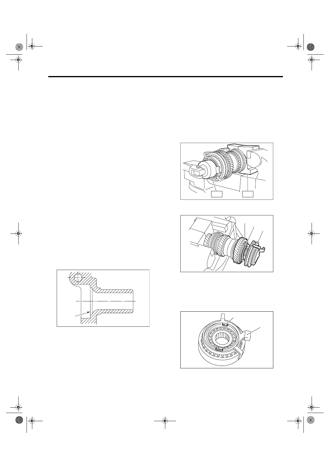
3) Remove the 5th-Rev sleeve & hub assembly,
baulk ring, 5th drive gear & needle bearing.
4) Remove the snap ring and synchro cone stopper
from 5th-Rev sleeve & hub assembly.
MT-00185
(A)
(A) 5th-Rev sleeve & hub ASSY
(B) Baulk ring
(C) 5th drive gear
(A) Synchro cone stopper
(B) Snap ring
MT-00186
ST2
ST1
MT-00187
( A )
( B )
( C )
MT-00188
(A)
(B)
5MT-62
MANUAL TRANSMISSION AND DIFFERENTIAL
Main Shaft Assembly for Single-Range
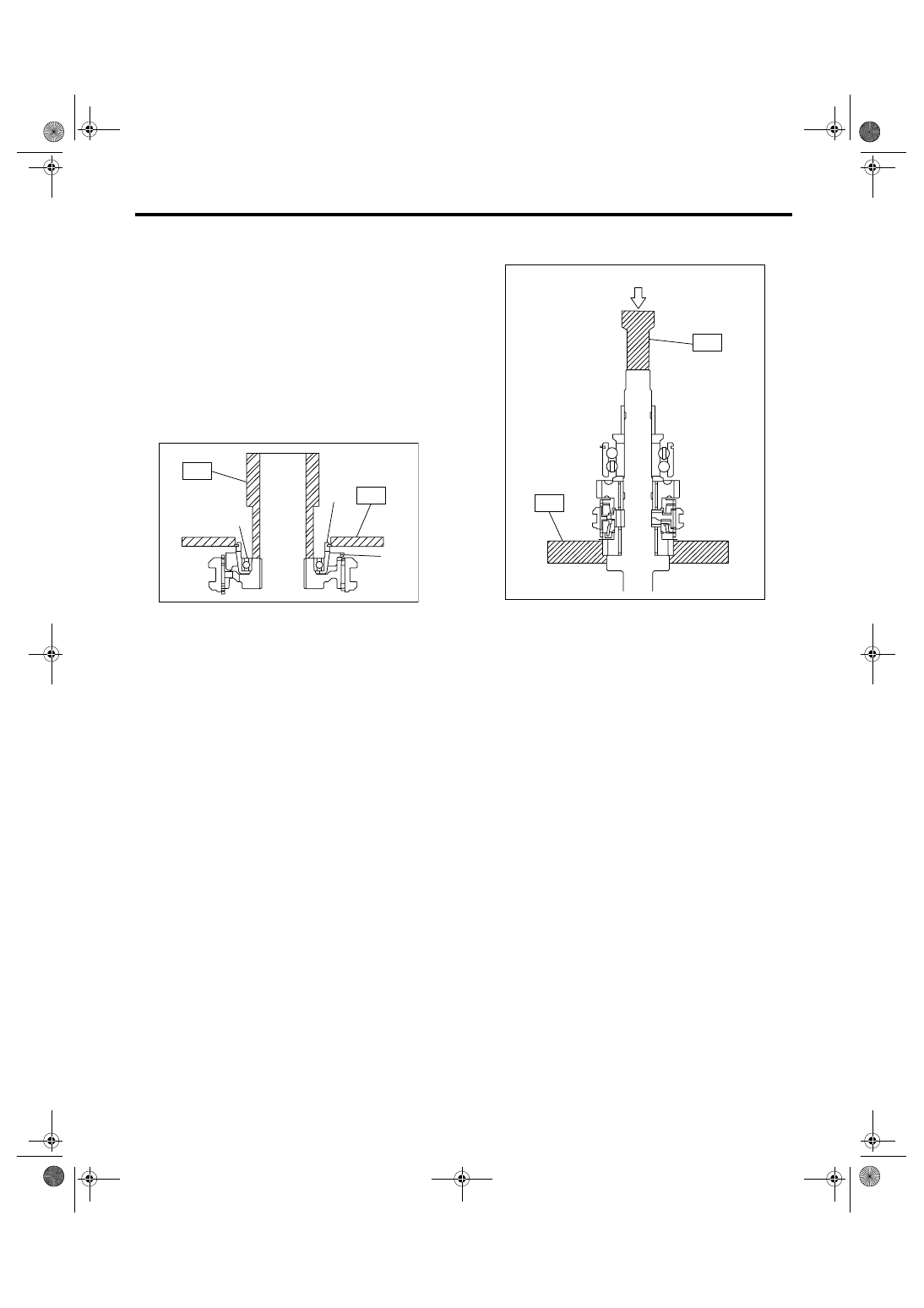
5) Using the ST1, ST2 and a press, remove the ball
bearing, synchro cone and baulk ring (Rev).
NOTE:
• When replacing the sleeve & hub with new ones,
replace them as a set.
• Do not disassemble the sleeve & hub, because
the aligning position is specified.
• If it is necessary to disassemble, mark the en-
gaging points on the splines beforehand.
• Do not reuse the ball bearing.
ST1
499757002
INSTALLER
ST2
498077400
SYNCHRO CONE REMOV-
ER
6) Using the ST1 and ST2, remove the rest of
parts.
NOTE:
• When replacing the sleeve & hub with new ones,
replace them as a set.
• Do not disassemble the sleeve & hub, because
the aligning position is specified.
• If it is necessary to disassemble, mark the en-
gaging points on the splines beforehand.
ST1
899864100
REMOVER
ST2
899714110
REMOVER
(A) Ball bearing
(B) Synchro cone
(C) Baulk ring
MT-00189
(B)
(A)
(C)
ST2
ST1
(A) Push
MT-00190
(A)
ST2
ST1
Нет комментариевНе стесняйтесь поделиться с нами вашим ценным мнением.
Текст