Subaru Legacy (2005 year). Service manual — part 636
5AT(diag)-135
AUTOMATIC TRANSMISSION (DIAGNOSTICS)
Diagnostic Procedure without Diagnostic Trouble Code (DTC)
C: CHECK BUZZER
DIAGNOSIS:
Output signal circuit of buzzer is open or shorted.
TROUBLE SYMPTOM:
Buzzer remains beeping.
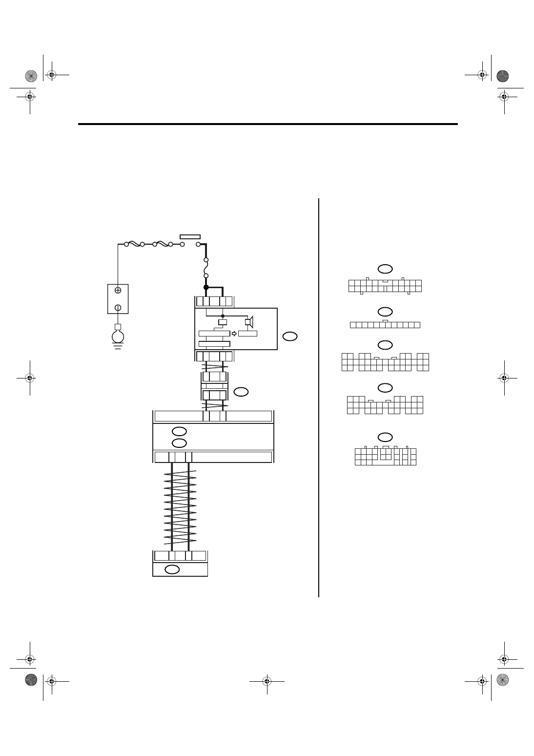
WIRING DIAGRAM:
3
4
21
22
AT-03178
1
7
i77
i10
i84
A:
B280
B:
2
8
A26
A27
B20
B30
4
3
TCM
B54
i10
i77
i84
B280
2
1
3 4
6 7 8 9 10
22
21
20
19
18
17
16
15
14
13
12
11
5
12
11
10
9
8
7
6
5
4
3
2
1
8
7
6
5
4
3
2
1
22 23
21
20
19
16
15
14
13
12
11
10
9
34 35
33
32
17
30
18
31
29
28
27
26
25
24
8
7
6
5
4
3
2
1
22
23
21
20
19
16
15
14
13
12
11
10
9
17
30
18
29
28
27
26
25
24
MAIN SBF
SBF-6
E
B
A
TTER
Y
IGNITION
SWITCH
JOINT
CONNECTOR
BODY INTEGRATED MODULE
COMBINATION
METER
SPORT
SHIFT
BUZZER
A:
B:
B54
1 2
7
8
9
5 6
3 4
10 11 12
19 20 21
13
14 15
16
17
18
22
23
24
No.5

5AT(diag)-136
AUTOMATIC TRANSMISSION (DIAGNOSTICS)
Diagnostic Procedure without Diagnostic Trouble Code (DTC)
Step
Check
Yes
No
1
CHECK BODY INTEGRATED MODULE.
Check DTC of body integrated module.
Is DTC of AT CAN communica-
tion circuit displayed?
Perform the diag-
nosis according to
DTC.
2
CHECK TCM.
Check DTC of TCM.
Is DTC of AT CAN communica-
tion circuit displayed?
Perform the diag-
nosis according to
DTC.
3
CHECK BUZZER STOP.
Disconnect the connector (B54).
Does the buzzer stop?
Replace the TCM.
<Ref. to 5AT-61,
Transmission Con-
trol Module
(TCM).>
4
CHECK BODY INTEGRATED MODULE.
1) Turn the ignition switch to OFF.
2) Connect the Subaru Select Monitor to data
link connector.
3) Turn the ignition switch to ON. (engine
OFF)
4) Turn the Subaru Select Monitor power
switch to ON.
5) Read the data of SPORT shift buzzer using
Subaru Select Monitor.
Is the SPORT shift buzzer dis-
play “ON”?
Replace the body
integrated mod-
ule. <Ref. to SL-
44, Body Inte-
grated Module.>
5
CHECK COMBINATION METER.
Is the buzzer OK?
Refer to “General
Diagnostic Table”.
<Ref. to 5AT(diag)-
137, General Diag-
nostic Table.>
Replace the com-
bination meter
assembly. <Ref. to
IDI-15, Combina-
tion Meter.>

5AT(diag)-137
AUTOMATIC TRANSMISSION (DIAGNOSTICS)
General Diagnostic Table
16.General Diagnostic Table
A: INSPECTION
Symptom
Problem parts
Shifting vehicle speed is low on “D” range.
• Vehicle speed sensor 1 and Vehicle speed sensor 2
• Accelerator pedal position sensor
• Throttle position sensor
• ATF temperature sensor
• CAN communication signal
Shifting vehicle speed is high on “D” range.
• Vehicle speed sensor 1 and Vehicle speed sensor 2
• Accelerator pedal position sensor
• Throttle position sensor
• CAN communication signal
• Brake switch signal
• Lateral G sensor
• ATF temperature sensor
Excessive shock. (“N”
→“D” range)
• Engine idle speed
• Engine speed signal
• Accelerator pedal position sensor
• Throttle position sensor
• Control cable adjustment
• ATF temperature sensor
• Oil pressure switch 1 and Front brake solenoid valve
• CAN communication signal
• Fluid level and condition
• TCM power supply
• PVIGN relay
Excessive shift shock on 1st of “D” range
→ 2nd of “D” range or
“1st of manual mode”
→ “2nd of manual mode”.
• Accelerator pedal position sensor
• Throttle position sensor
• Control cable adjustment
• Oil pressure switch 4 and Direct clutch solenoid valve
• CAN communication signal
• Engine speed signal
• Torque converter turbine speed sensor
• Vehicle speed sensor 1 and Vehicle speed sensor 2
• Fluid level and condition
Excessive shift shock on 2nd of “D” range
→ 3rd of “D” range or
“2nd of manual mode”
→ “3rd of manual mode”.
• Accelerator pedal position sensor
• Throttle position sensor
• Control cable adjustment
• Oil pressure switch 5 and High & low reverse clutch solenoid
valve
• CAN communication signal
• Engine speed signal
• Torque converter turbine speed sensor
• Vehicle speed sensor 1 and Vehicle speed sensor 2
• Fluid level and condition
Excessive shift shock on 3rd of “D” range
→ 4th of “D” range or
“3rd of manual mode”
→ “4th of manual mode”.
• Accelerator pedal position sensor
• Throttle position sensor
• Control cable adjustment
• Oil pressure switch 3 and Input clutch solenoid valve
• CAN communication signal
• Engine speed signal
• Torque converter turbine speed sensor
• Vehicle speed sensor 1 and Vehicle speed sensor 2
• Fluid level and condition
5AT(diag)-138
AUTOMATIC TRANSMISSION (DIAGNOSTICS)
General Diagnostic Table
Excessive shift shock on 4th of “D” range
→ 5th of “D” range or
“4th of manual mode”
→ “5th of manual mode”.
• Accelerator pedal position sensor
• Throttle position sensor
• Control cable adjustment
• Oil pressure switch 1 and Front brake solenoid valve
• CAN communication signal
• Engine speed signal
• Torque converter turbine speed sensor
• Vehicle speed sensor 1 and Vehicle speed sensor 2
• Fluid level and condition
Excessive shock at kick down.
• Accelerator pedal position sensor
• Throttle position sensor
• Control cable adjustment
• CAN communication signal
• Engine speed signal
• Torque converter turbine speed sensor
• Vehicle speed sensor 1 and Vehicle speed sensor 2
• Fluid level and condition
Excessive shock at shift up.
• Accelerator pedal position sensor
• Throttle position sensor
• Control cable adjustment
• Engine speed signal
• CAN communication signal
• Torque converter turbine speed sensor
• Vehicle speed sensor 1 and Vehicle speed sensor 2
• Fluid level and condition
Excessive shock at lock up.
• Accelerator pedal position sensor
• Throttle position sensor
• Control cable adjustment
• Engine speed signal
• CAN communication signal
• Torque converter turbine speed sensor
• Lock up solenoid valve
• Vehicle speed sensor 1 and Vehicle speed sensor 2
• Fluid level and condition
Excessive shock at engine brake.
• Accelerator pedal position sensor
• Throttle position sensor
• Control cable adjustment
• CAN communication signal
• Fluid level and condition
• Line pressure
• Low coast brake solenoid valve
Judder is occurred at lock up.
• Fluid level and condition
• Engine speed signal
• Torque converter turbine speed sensor
• Vehicle speed sensor 1 and Vehicle speed sensor 2
• Accelerator pedal position sensor
• Throttle position sensor
• Lock up solenoid valve
• ATF temperature sensor 1 and 2
Noise at “R”, “N” and “D” range.
• Fluid level and condition
• Engine speed signal
• ATF temperature sensor 1 and 2
Hold at “D” range or 1st on manual mode.
• Fluid level and condition
• Vehicle speed sensor 1 and Vehicle speed sensor 2
• Direct clutch solenoid valve
• Line pressure
• Up switch signal
• CAN communication signal
• Accelerator pedal position sensor
Symptom
Problem parts
Нет комментариевНе стесняйтесь поделиться с нами вашим ценным мнением.
Текст