Subaru Legacy (2005 year). Service manual — part 873
AC(diag)-9
HVAC SYSTEM (AUTO A/C) (DIAGNOSTICS)
Auto A/C Control Module I/O Signal
*1: Unable to measure the voltage for digital signal.
B: WIRING DIAGRAM
1. AIR CONDITIONER AUTO A/C MODEL
<Ref. to WI-189, WIRING DIAGRAM, Air Conditioning System.>
B15, B16
Control panel
—
*1
Terminal No.
Remarks
Measuring conditions
Specification
AC(diag)-10
HVAC SYSTEM (AUTO A/C) (DIAGNOSTICS)
Diagnostic Chart for Self-Diagnosis
5. Diagnostic Chart for Self-Diagnosis
A: OPERATION
NOTE:
For A/C system self-diagnosis, there is one that checks the control panel, and the other that checks the whole
control system (sensor, actuator, blower motor, etc.). Perform the self-diagnosis for control panel first, and
then perform the self-diagnosis for control system.
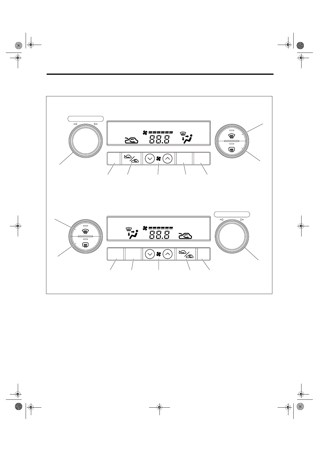
(A)
LHD model
(B)
RHD model
(1)
Defroster switch
(4)
A/C switch
(7)
OFF switch
(2)
Rear window defogger switch
(5)
Fan switch
(8)
Temperature control dial (AUTO
switch)
(3)
Air flow control switch
(6)
FRESH/RECIRC switch
AC-01253
(8)
(7)
(6)
(5)
(4)
(3)
(2)
A/C
A/C
OFF
MODE
AUTO
PUSH AUTO/TEMP
(1)
(3)
(4)
(5)
(6)
(7)
A/C
(2)
(1)
(8)
PUSH AUTO/TEMP
A/C
MODE
OFF
AUTO
(A)
(B)
AC(diag)-11
HVAC SYSTEM (AUTO A/C) (DIAGNOSTICS)
Diagnostic Chart for Self-Diagnosis
1. A/C CONTROL PANEL SELF-DIAGNOSIS
Step
Check
Yes
No
1
SET SELF-DIAGNOSIS MODE BY OPERAT-
ING A/C CONTROL PANEL.
1) Turn the ignition switch to OFF.
2) Turn the ignition switch to ON with the
defroster switch and A/C switch pressed.
3) The screen display and indicator illuminate.
Does the self-diagnosis mode
operate?
2
CHECK DISPLAY AND INDICATOR.
Check the display and all indicators illuminate.
Do the display and all indica-
tors illuminate?
Replace the A/C
control panel.
3
CHECK SWITCH AND TEMPERATURE CON-
TROL DIAL INPUT.
According to the switch check table, press
each switch or turn the temperature control
dial, and check the relative screen display and
indicators illuminate. <Ref. to AC(diag)-12,
SWITCH CHECK TABLE, OPERATION, Diag-
nostic Chart for Self-Diagnosis.>
Does the screen display
related to each switch and dial
input illuminate?
Replace the A/C
control panel.
4
CHECK A/C CONTROL PANEL COMMUNI-
CATION.
1) Turn the ignition switch to OFF.
2) Disconnect the auto A/C control module
harness connector.
3) Using a suitable lead wire, short the termi-
nal No. 15 and No. 16 of auto A/C control mod-
ule harness connector (B283).
4) Turn the ignition switch to ON with the rear
defogger switch and A/C switch pressed.
5) When no malfunction occurs in the control
panel communication, “CL” is displayed in the
screen; and when malfunction occurs, “OP” is
displayed.
Is “CL” displayed in the
screen?
A/C control panel
is normal. Turn the
ignition switch to
OFF, and connect
the auto A/C con-
trol module har-
ness connector.
Replace the A/C
control panel.
AC(diag)-12
HVAC SYSTEM (AUTO A/C) (DIAGNOSTICS)
Diagnostic Chart for Self-Diagnosis
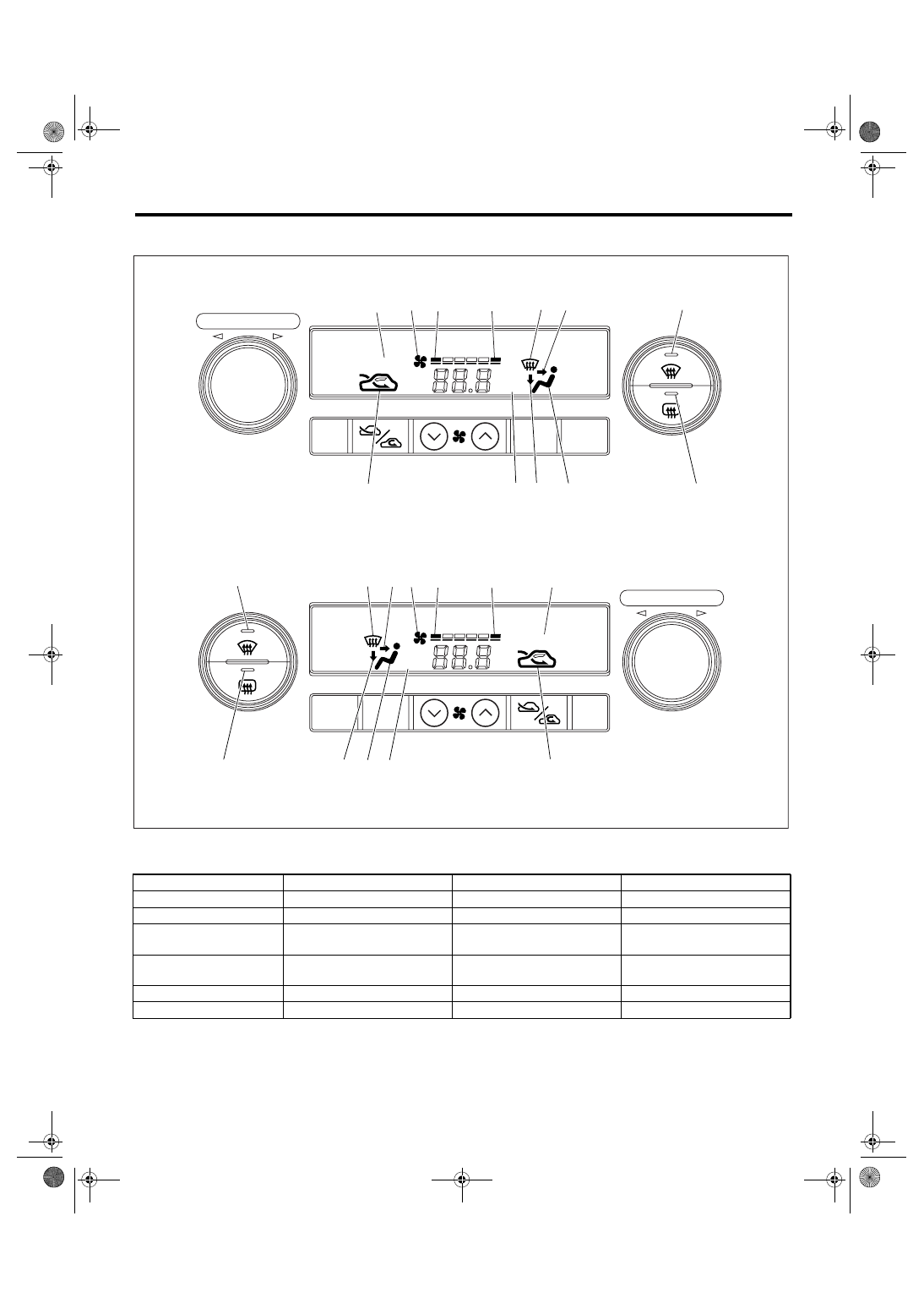
2. SWITCH CHECK TABLE
(A)
LHD model
(B)
RHD model
Switch
Display screen
Switch
Display screen
A/C switch
(9)
FAN switch (+)
(6)
AUTO switch
(7)
FAN switch (
−)
(5)
Air flow control switch
(10)
Temperature control dial (Right
turn)
(3)
FRESH/RECIRC
(8)
Temperature control dial (Left
turn)
(11)
Defroster switch
(1) (2)
OFF switch
(4)
Rear defogger switch
(12)
AC-00902
A/C
OFF
MODE
PUSH AUTO/TEMP
PUSH AUTO/TEMP
A/C
MODE
OFF
(A)
(B)
(8)
(10)
(11)
(9)
(2)
(3) (4)
(5)
(6)
(7)
A/C
AUTO
(4)
(5)
(6)
(8)
(7)
AUTO
(9)
A/C
(10)
(11)
(2)
(3)
(1)
(12)
(1)
(12)
Нет комментариевНе стесняйтесь поделиться с нами вашим ценным мнением.
Текст