Subaru Legacy (2005 year). Service manual — part 872
AC(diag)-5
HVAC SYSTEM (AUTO A/C) (DIAGNOSTICS)
Electrical Component Location
3. Electrical Component Location
A: LOCATION
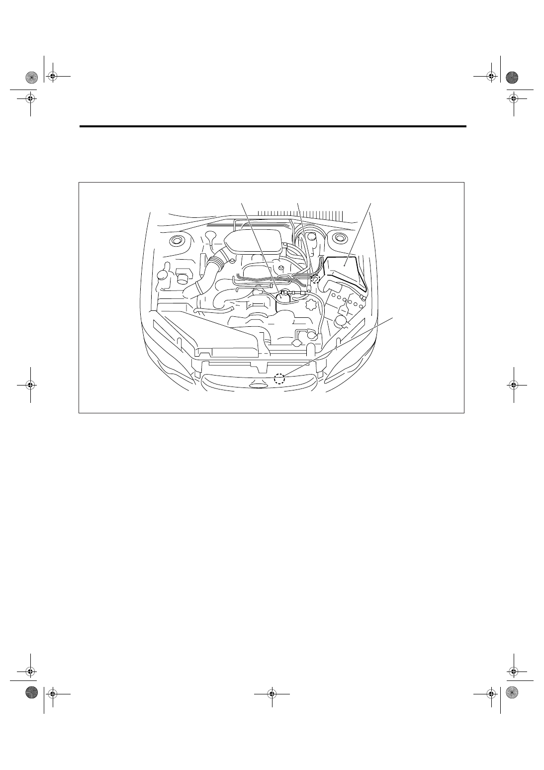
1. ENGINE COMPARTMENT
(1)
A/C compressor
(3)
Pressure switch
(4)
Ambient sensor
(2)
A/C relay
AC-00896
(2)
(4)
(1)
(3)
AC(diag)-6
HVAC SYSTEM (AUTO A/C) (DIAGNOSTICS)
Electrical Component Location
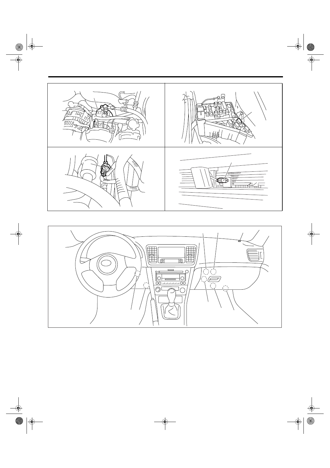
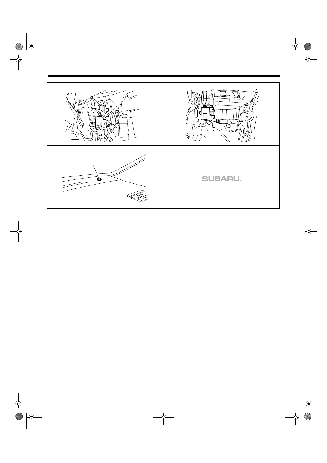
2. PASSENGER COMPARTMENT
(1)
Evaporator sensor
(4)
Blower motor
(7)
Mode door actuator
(2)
Air mix door actuator
(5)
Sunload sensor
(8)
In-vehicle sensor
(3)
Auto A/C control module
(6)
Intake door actuator
AC-00813
(1)
AC-00815
(2)
AC-00814
(3)
AC-00816
(4)
(7)
(6)
(4)
(3)
(2)
(1)
(8)
(5)
AC-00897
AC(diag)-7
HVAC SYSTEM (AUTO A/C) (DIAGNOSTICS)
Electrical Component Location
AC-00898
(1)
(2)
(7)
(3)
(4)
(6)
AC-00900
AC-00899
(5)
AC(diag)-8
HVAC SYSTEM (AUTO A/C) (DIAGNOSTICS)
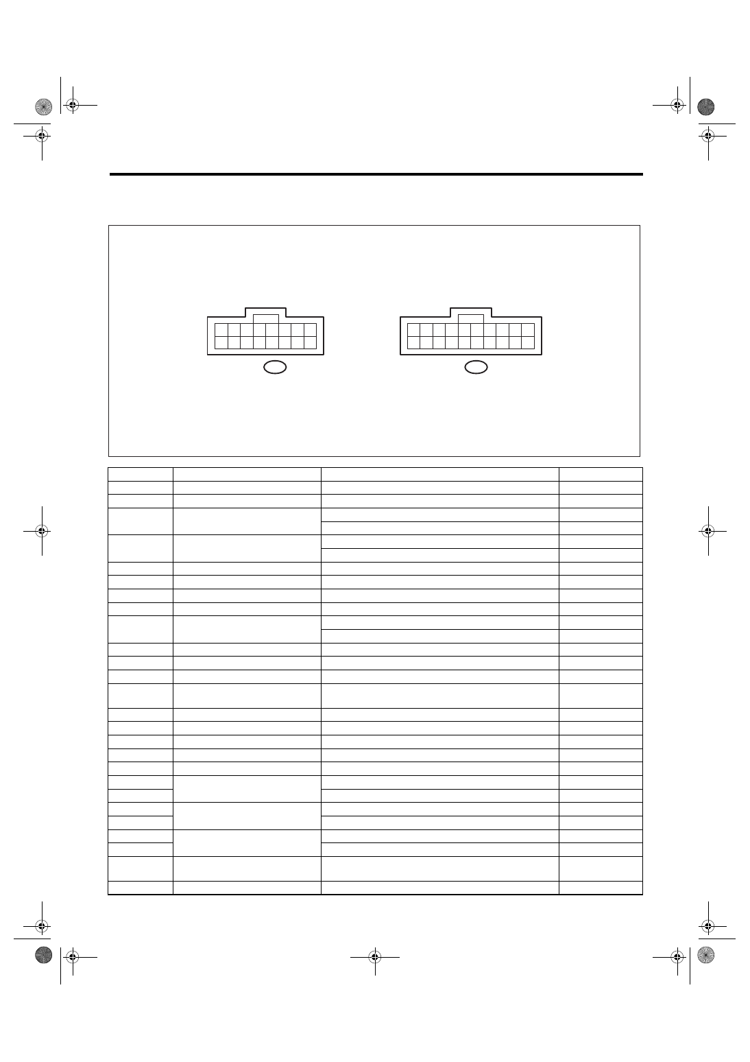
Auto A/C Control Module I/O Signal
4. Auto A/C Control Module I/O Signal
A: ELECTRICAL SPECIFICATION
Terminal No.
Remarks
Measuring conditions
Specification
A1
Battery power supply
Ignition switch: OFF
Battery voltage
A2
ACC power supply
Ignition switch: ACC
Battery voltage
A3
Mode door actuator position sig-
nal
Mode door: FACE position
4 V
Mode door: DEF position
1 V
A4
Air mix door actuator position sig-
nal
Air mix door: Maximum cool position
4 V
Air mix door: Maximum hot position
1 V
A5
In-vehicle sensor
Ignition switch: ON
Less than 5 V
A6
Sunload sensor
Ignition switch: ON, With sunload (No sunload: 0 V)
3 V
A8
Sensor power supply
Ignition switch: ON
5 V
A9
Ignition power supply
Ignition switch: ON
Battery voltage
A10
A/C cut signal
Ignition switch: ON
Battery voltage
When operating pressure SW
0 V
A13
Evaporator center
Ignition switch: ON
Less than 5 V
A14, A16
Ground
Continuity to chassis ground
0
Ω
A15
Sensor ground
Continuity to chassis ground
0
Ω
B1, B11
Ambient sensor, engine coolant
temperature sensor
—
*1
B2
Blower motor control
Ignition switch : ON, Blower switch : ON
0.45 V
B3
Blower motor control
Ignition switch : ON, Blower switch : ON
9.05 V
B4
RAM monitor
—
*1
B5
RAM monitor
—
*1
B6
A/C ON signal
A/C ON (A/C OFF: 0 V)
7 — 14 V
B7
Mode door actuator power supply
When switching mode door from DEF
→ FACE
Battery voltage
B17
When switching mode door from FACE
→ DEF
Battery voltage
B8
Air mix door actuator power sup-
ply
When switching air mix door from HOT
→ COOL
Battery voltage
B18
When switching air mix door from COOL
→ HOT
Battery voltage
B10
Intake door actuator
FRESH (RECIRC: Battery voltage)
0 V
B20
RECIRC (FRESH: Battery voltage)
0 V
B13
Blower fan ON signal
When blower fan is rotating (Not rotating: Battery volt-
age)
0 V
B14
RAM monitor
—
*1
AC-00735
10
20 19 18 17 16 15 14 13 12 11
9
8
7
6
5
4
3
2
1
10
16 15 14 13 12 11
9
8
7
6
5
4
3
2
1
To B: B283
To A: B282
Нет комментариевНе стесняйтесь поделиться с нами вашим ценным мнением.
Текст