Subaru Legacy (2005 year). Service manual — part 217
EN(H4SO 2.5)(diag)-153
ENGINE (DIAGNOSTICS)
Diagnostic Procedure with Diagnostic Trouble Code (DTC)
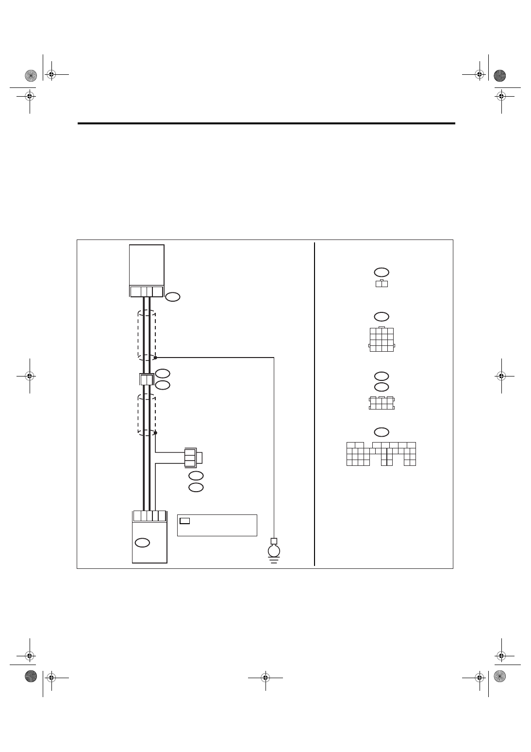
AH:DTC P0335 CRANKSHAFT POSITION SENSOR “A” CIRCUIT
DTC DETECTING CONDITION:
Immediately at fault recognition
TROUBLE SYMPTOM:
• Engine stalls.
• Failure of engine to start
CAUTION:
After repair or replacement of faulty parts, conduct Clear Memory Mode <Ref. to EN(H4SO 2.5)(diag)-
40, Clear Memory Mode.> and Inspection Mode <Ref. to EN(H4SO 2.5)(diag)-33, Inspection Mode.>.
WIRING DIAGRAM:
• EC, EK, EH, ER and K4 model
• KA and KS model
NOTE:
Fuel injection system for KA and KS model is the same as 2.0 L model. Refer to EN(H4SO 2.0) section.
EN-03463
1
2
8
7
22
31
B20
E1
E10
E10
1 2
B135
ECM
CRANKSHAFT
POSITION
SENSOR
10
E
B20
1 2 3 4
5 6 7 8
B122
B138
B135
5
6
7
8
2
1
9
4
3
10
24
22 23
25
11 12 13 14 15
26 27
28
16 17 18 19
20 21
29 30 31
32 33
34 35
B122 : RHD
B138 : LHD
1 2 3 4
5 6 7 8
9 10 11 12
14
13
15 16
*
: TERMINAL No. RANDOM
ARRANGEMENT
AMONG 3,4,7, AND 8
*
*
EN(H4SO 2.5)(diag)-154
ENGINE (DIAGNOSTICS)
Diagnostic Procedure with Diagnostic Trouble Code (DTC)
Step
Check
Yes
No
1
CHECK OPTION CODE.
Is the option code EC, EK, EH,
ER or K4?
Refer to EN(H4SO
2.0) section. <Ref.
to EN(H4SO
2.0)(diag)-64, List
of Diagnostic Trou-
ble Code (DTC).>
NOTE:
Fuel injection sys-
tem for KA and KS
model is the same
as 2.0 L model.
2
CHECK HARNESS BETWEEN CRANK-
SHAFT POSITION SENSOR AND ECM CON-
NECTOR.
1) Turn the ignition switch to OFF.
2) Disconnect the connector from crankshaft
position sensor.
3) Measure the resistance of harness
between crankshaft position sensor connector
and engine ground.
Connector & terminal
(E10) No. 1 — Engine ground:
Is the resistance more than
100 k
Ω?
Repair the har-
ness and connec-
tor.
NOTE:
In this case, repair
the following:
• Open circuit of
harness between
crankshaft posi-
tion sensor and
ECM connector
• Poor contact in
ECM connector
• Poor contact in
coupling connector
3
CHECK HARNESS BETWEEN CRANK-
SHAFT POSITION SENSOR AND ECM CON-
NECTOR.
Measure the resistance of harness between
crankshaft position sensor connector and
engine ground.
Connector & terminal
(E10) No. 1 — Engine ground:
Is the resistance less than 10
Ω?
Repair the ground
short circuit of har-
ness between
crankshaft posi-
tion sensor and
ECM connector.
NOTE:
The harness be-
tween both con-
nectors are
shielded. Repair
the ground short
circuit of harness
with shield.
4
CHECK HARNESS BETWEEN CRANK-
SHAFT POSITION SENSOR AND ECM CON-
NECTOR.
Measure the resistance of harness between
crankshaft position sensor connector and
engine ground.
Connector & terminal
(E10) No. 2 — Engine ground:
Is the resistance less than 5
Ω?
Repair the har-
ness and connec-
tor.
NOTE:
In this case, repair
the following:
• Open circuit of
harness between
crankshaft posi-
tion sensor and
ECM connector
• Poor contact in
ECM connector
• Poor contact in
coupling connector
5
CHECK CONDITION OF CRANKSHAFT PO-
SITION SENSOR.
Is the crankshaft position sen-
sor installation bolt tightened
securely?
Tighten the crank-
shaft position sen-
sor installation bolt
securely.

EN(H4SO 2.5)(diag)-155
ENGINE (DIAGNOSTICS)
Diagnostic Procedure with Diagnostic Trouble Code (DTC)
6
CHECK CRANKSHAFT POSITION SENSOR.
1) Remove the crankshaft position sensor.
2) Measure the resistance between connector
terminals of crankshaft position sensor.
Terminals
No. 1 — No. 2:
Is the resistance 1 — 4 k
Ω?
Repair the poor
contact in crank-
shaft position sen-
sor connector.
Replace the crank-
shaft position sen-
sor. <Ref. to
FU(H4SO 2.5)-21,
Crankshaft Posi-
tion Sensor.>
Step
Check
Yes
No
EN(H4SO 2.5)(diag)-156
ENGINE (DIAGNOSTICS)
Diagnostic Procedure with Diagnostic Trouble Code (DTC)
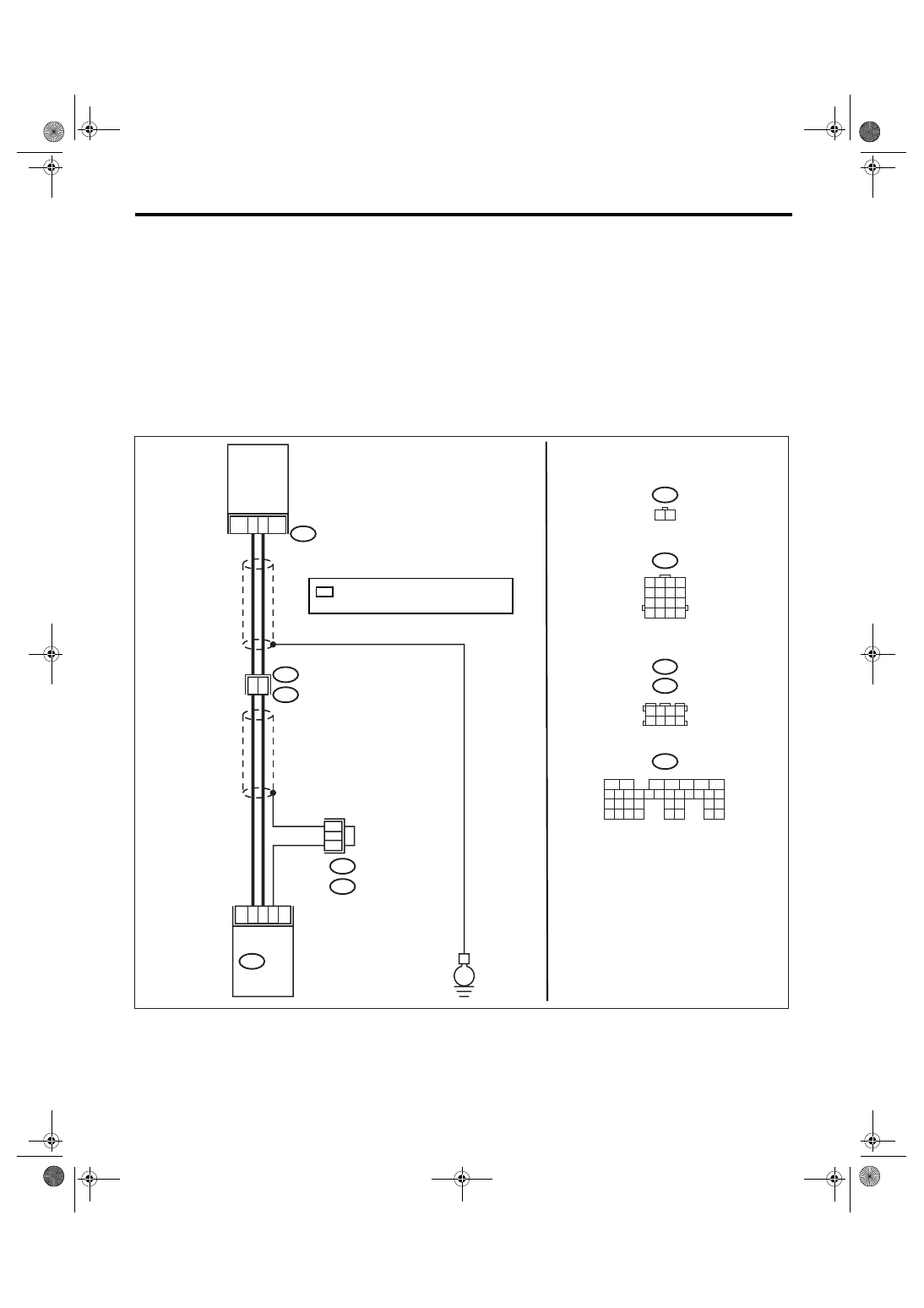
AI: DTC P0340 CAMSHAFT POSITION SENSOR “A” CIRCUIT (BANK 1 OR SIN-
GLE SENSOR)
DTC DETECTING CONDITION:
Immediately at fault recognition
TROUBLE SYMPTOM:
• Engine stalls.
• Failure of engine to start
CAUTION:
After repair or replacement of faulty parts, conduct Clear Memory Mode <Ref. to EN(H4SO 2.5)(diag)-
40, Clear Memory Mode.> and Inspection Mode <Ref. to EN(H4SO 2.5)(diag)-33, Inspection Mode.>.
WIRING DIAGRAM:
• EC, EK, EH, ER and K4 model
• KA and KS model
NOTE:
Fuel injection system for KA and KS model is the same as 2.0 L model. Refer to EN(H4SO 2.0) section.
EN-03513
E15
1 2
1
2
6
5
23
31
B20
E1
E15
B135
ECM
CAMSHAFT
POSITION
SENSOR
11
E
B20
1 2 3 4
5 6 7 8
B122
B138
B135
5
6
7
8
2
1
9
4
3
10
24
22 23
25
11 12 13 14 15
26 27
28
16 17 18 19
20 21
29 30 31
32 33
34 35
B122 : RHD
B138 : LHD
1 2 3 4
5 6 7 8
9 10 11 12
14
13
15 16
*
*
*
: TERMINAL No. RANDOM ARRANGEMENT
AMONG 3,4,7, AND 8
Нет комментариевНе стесняйтесь поделиться с нами вашим ценным мнением.
Текст