Subaru Legacy (2005 year). Service manual — part 218

EN(H4SO 2.5)(diag)-157
ENGINE (DIAGNOSTICS)
Diagnostic Procedure with Diagnostic Trouble Code (DTC)
Step
Check
Yes
No
1
CHECK OPTION CODE.
Is the option code EC, EK, EH,
ER or K4?
Refer to EN(H4SO
2.0) section. <Ref.
to EN(H4SO
2.0)(diag)-64, List
of Diagnostic Trou-
ble Code (DTC).>
NOTE:
Fuel injection sys-
tem for KA and KS
model is the same
as 2.0 L model.
2
CHECK HARNESS BETWEEN CAMSHAFT
POSITION SENSOR AND ECM CONNEC-
TOR.
1) Turn the ignition switch to OFF.
2) Disconnect the connector from camshaft
position sensor.
3) Measure the resistance of harness
between camshaft position sensor connector
and engine ground.
Connector & terminal
(E15) No. 1 — Engine ground:
Is the resistance more than
100 k
Ω?
Repair the har-
ness and connec-
tor.
NOTE:
In this case, repair
the following:
• Open circuit of
harness between
camshaft position
sensor and ECM
connector
• Poor contact in
ECM connector
• Poor contact in
coupling connector
3
CHECK HARNESS BETWEEN CAMSHAFT
POSITION SENSOR AND ECM CONNEC-
TOR.
Measure the resistance of harness between
camshaft position sensor connector and
engine ground.
Connector & terminal
(E15) No. 1 — Engine ground:
Is the resistance less than 10
Ω?
Repair the ground
short circuit of har-
ness between
camshaft position
sensor and ECM
connector.
NOTE:
The harness be-
tween both con-
nectors are
shielded. Repair
the ground short
circuit of harness
with shield.
4
CHECK HARNESS BETWEEN CAMSHAFT
POSITION SENSOR AND ECM CONNEC-
TOR.
Measure the resistance of harness between
camshaft position sensor connector and
engine ground.
Connector & terminal
(E15) No. 2 — Engine ground:
Is the resistance less than 5
Ω?
Repair the har-
ness and connec-
tor.
NOTE:
In this case, repair
the following:
• Open circuit of
harness between
camshaft position
sensor and ECM
connector
• Poor contact in
ECM connector
• Poor contact in
coupling connector
5
CHECK CONDITION OF CAMSHAFT POSI-
TION SENSOR.
Is the camshaft position sensor
installation bolt tightened
securely?
Tighten the cam-
shaft position sen-
sor installation bolt
securely.

EN(H4SO 2.5)(diag)-158
ENGINE (DIAGNOSTICS)
Diagnostic Procedure with Diagnostic Trouble Code (DTC)
6
CHECK CAMSHAFT POSITION SENSOR.
1) Remove the camshaft position sensor.
2) Measure the resistance between connector
terminals of camshaft position sensor.
Terminals
No. 1 — No. 2:
Is the resistance 1 — 4 k
Ω?
Repair the poor
contact in cam-
shaft position sen-
sor connector.
Replace the cam-
shaft position sen-
sor. <Ref. to
FU(H4SO 2.5)-22,
Camshaft Position
Sensor.>
Step
Check
Yes
No
EN(H4SO 2.5)(diag)-159
ENGINE (DIAGNOSTICS)
Diagnostic Procedure with Diagnostic Trouble Code (DTC)
AJ:DTC P0400 EXHAUST GAS RECIRCULATION FLOW
DTC DETECTING CONDITION:
Detects when malfunction occurs in 2 continuous driving cycles.
TROUBLE SYMPTOM:
• Movement performance problem when engine is low speed.
• Erroneous idling
• Movement performance problem
CAUTION:
After repair or replacement of faulty parts, conduct Clear Memory Mode <Ref. to EN(H4SO 2.5)(diag)-
40, Clear Memory Mode.> and Inspection Mode <Ref. to EN(H4SO 2.5)(diag)-33, Inspection Mode.>.
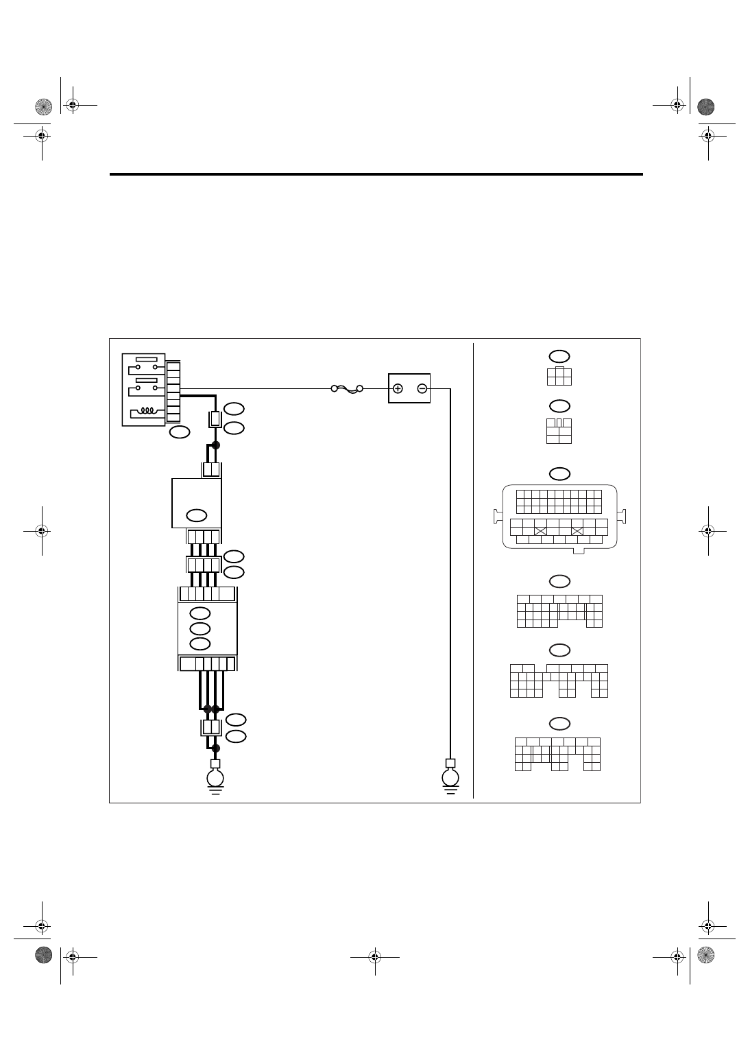
WIRING DIAGRAM:
EN-03464
E
E
B47
E18
2
5
1
4
3
6
B21
E2
B21
E2
B21
E2
5
3
6
2
1
48
26
A10
A9
A11
A8
D2
D1
B4
25
29
30
35
36
SBF-7
BATTERY
MAIN RELAY
EGR
VALVE
A: B134
B: B135
D: B137
ECM
B47
E18
3
4
1
2
5
6
1
3
4 5 6
2
B1
B21
1 2 3 4
12 13 14 15
5 6 7 8
16 17 18 19
9 10 11
20 21 22
23 24 25 26 27 28 29 30 31 32 33
35
34
37
36
39
38
41
40
43
42
44
45
47
46
49
48
51
50
53
52
54
B137
5
6
7
8
2
1
9
4
3
10
22 23
11 12 13 14 15
24 25
26
16 17
18 19 20 21
27
28 29
30 31
B134
5
6
7
8
2
1
9
4
3
10
24
22 23
25
11 12 13 14 15
26 27
28
16 17
18 19 20 21
33 34
29
32
30 31
B135
5
6
7
8
2
1
9
4
3
10
24
22 23
25
11 12 13 14 15
26 27
28
16 17 18 19
20 21
29 30 31
32 33
34 35
A:
B:
D:
4

EN(H4SO 2.5)(diag)-160
ENGINE (DIAGNOSTICS)
Diagnostic Procedure with Diagnostic Trouble Code (DTC)
Step
Check
Yes
No
1
CHECK ANY OTHER DTC ON DISPLAY.
Is any other DTC displayed?
Check DTC using
“List of Diagnostic
Trouble Code
(DTC)”. <Ref. to
EN(H4SO
2.5)(diag)-69, List
of Diagnostic Trou-
ble Code (DTC).>
2
CHECK CURRENT DATA.
1) Start the engine.
2) Read the data of intake manifold absolute
pressure signal using Subaru Select Monitor or
general scan tool.
NOTE:
• Subaru Select Monitor
For detailed operation procedure, refer to
“READ CURRENT DATA FOR ENGINE”. <Ref.
to EN(H4SO 2.5)(diag)-25, Subaru Select
Monitor.>
• General scan tool
For detailed operation procedure, refer to the
general scan tool operation manual.
Is the measured value more
than 53.3 kPa (400 mmHg,
15.75 inHg)?
Make sure that the
EGR valve, mani-
fold absolute pres-
sure sensor and
throttle body are
installed securely.
3
CHECK POWER SUPPLY OF EGR SOLE-
NOID VALVE.
1) Disconnect the connector from EGR sole-
noid valve.
2) Turn the ignition switch to ON.
3) Measure the voltage between EGR sole-
noid valve and engine ground.
Connector & terminal
(E18) No. 2 (+) — Engine ground (
−
):
(E18) No. 5 (+) — Engine ground (
−
):
Is the voltage more than 10 V? Go to step 4.
Repair the open
circuit of harness
between main
relay and EGR
solenoid valve
connector.
4
CHECK EGR SOLENOID VALVE.
Measure the resistance between EGR sole-
noid valve terminals.
NOTE:
Make sure there is no foreign material between
EGR solenoid valve and valve seat.
Terminals
No. 1 — No. 2:
No. 3 — No. 2:
No. 4 — No. 5:
No. 6 — No. 5:
Is the resistance 20 — 30
Ω?
Replace the EGR
solenoid valve.
<Ref. to FU(H4SO
2.5)-31, EGR
Valve.>
5
CHECK OUTPUT SIGNAL FROM ECM.
1) Turn the ignition switch to OFF.
2) Connect the connector to ECM and EGR
solenoid valve.
3) Turn the ignition switch to ON.
4) Measure the voltage between ECM and
chassis ground.
Connector & terminal
(B134) No. 8 (+) — Chassis ground (
−
):
(B134) No. 9 (+) — Chassis ground (
−
):
(B134) No. 10 (+) — Chassis ground (
−
):
(B134) No. 11 (+) — Chassis ground (
−
):
Is the voltage 0 — 10 V?
Repair the poor
contact portion in
ECM connector.
Нет комментариевНе стесняйтесь поделиться с нами вашим ценным мнением.
Текст