Subaru Legacy (2005 year). Service manual — part 315
EN(H4DOTC)(diag)-29
ENGINE (DIAGNOSTICS)
Read Diagnostic Trouble Code (DTC)
10.Read Diagnostic Trouble
Code (DTC)
A: OPERATION
1. SUBARU SELECT MONITOR (NORMAL
MODE)
1) On the «Main Menu» display screen, select the
{Each System Check} and press the [YES] key.
2) On the «System Selection Menu» display
screen, select the {Engine} and press the [YES]
key.
3) Press the [YES] key after the information of en-
gine type has been displayed.
4) On the «Engine Diagnosis» screen, select the
{Diagnostic Code(s) Display}, and then press the
[YES] key.
5) On the «Diagnostic Code(s) Display» screen,
select the {Current Diagnostic Code(s)} or {History
Diagnostic Code(s)}, and then press the [YES] key.
NOTE:
• For detailed operation procedure, refer to the
SUBARU SELECT MONITOR OPERATION MAN-
UAL.
• For details concerning DTCs, refer to the List of
Diagnostic Trouble Code (DTC). <Ref. to
EN(H4DOTC)(diag)-62, List of Diagnostic Trouble
Code (DTC).>
2. SUBARU SELECT MONITOR (OBD
MODE)
1) On the «Main Menu» display screen, select the
{Each System Check} and press the [YES] key.
2) On the «System Selection Menu» display
screen, select the {Engine} and press the [YES]
key.
3) Press the [YES] key after the information of en-
gine type has been displayed.
4) On the «Engine Diagnosis» display screen, se-
lect the {OBD System} and press the [YES] key.
5) On the «OBD Menu» display screen, select the
{Diagnostic Code(s) Display} and press the [YES]
key.
6) Make sure DTC is shown on the screen.
NOTE:
• For detailed operation procedure, refer to the
SUBARU SELECT MONITOR OPERATION MAN-
UAL.
• For details concerning DTCs, refer to the List of
Diagnostic Trouble Code (DTC). <Ref. to
EN(H4DOTC)(diag)-62, List of Diagnostic Trouble
Code (DTC).>
3. GENERAL SCAN TOOL
Refer to the data denoting emission-related power-
train DTC.
For details concerning DTCs, refer to the List of Di-
agnostic Trouble Code (DTC). <Ref. to
EN(H4DOTC)(diag)-29, Read Diagnostic Trouble
Code (DTC).>
NOTE:
Refer to the general scan tool manufacturer’s oper-
ation manual to access powertrain DTC (MODE
$03).

EN(H4DOTC)(diag)-30
ENGINE (DIAGNOSTICS)
Inspection Mode
11.Inspection Mode
A: PROCEDURE
Carry out trouble diagnosis shown in the following DTC table.
When performing trouble diagnosis which is not shown in the DTC table, refer to the next item Drive cycle.
<Ref. to EN(H4DOTC)(diag)-35, Drive Cycle.>
DTC
Item
P0031
HO2S Heater Control Circuit Low (Bank 1 Sensor 1)
P0032
HO2S Heater Control Circuit High (Bank 1 Sensor 1)
P0037
HO2S Heater Control Circuit Low (Bank 1 Sensor 2)
P0038
HO2S Heater Control Circuit High (Bank 1 Sensor 2)
P0102
Mass or Volume Air Flow Circuit Low Input
P0103
Mass or Volume Air Flow Circuit High Input
P0107
Manifold Absolute Pressure/Barometric Pressure Circuit Low Input
P0108
Manifold Absolute Pressure/Barometric Pressure Circuit High Input
P0112
Intake Air Temperature Sensor 1 Circuit Low
P0113
Intake Air Temperature Sensor 1 Circuit High
P0117
Engine Coolant Temperature Circuit Low
P0118
Engine Coolant Temperature Circuit High
P0122
Throttle/Pedal Position Sensor/Switch “A” Circuit Low
P0123
Throttle/Pedal Position Sensor/Switch “A” Circuit High
P0131
O2 Sensor Circuit Low Voltage (Bank 1 Sensor 1)
P0132
O2 Sensor Circuit High Voltage (Bank 1 Sensor 1)
P0137
O2 Sensor Circuit Low Voltage (Bank 1 Sensor 2)
P0138
O2 Sensor Circuit High Voltage (Bank 1 Sensor 2)
P0222
Throttle/Pedal Position Sensor/Switch “B” Circuit Low
P0223
Throttle/Pedal Position Sensor/Switch “B” Circuit High
P0230
Fuel Pump Primary Circuit
P0245
Turbo/Super Charger Wastegate Solenoid “A” Low
P0261
Cylinder 1 Injector Circuit Low
P0264
Cylinder 2 Injector Circuit Low
P0267
Cylinder 3 Injector Circuit Low
P0270
Cylinder 4 Injector Circuit Low
P0327
Knock Sensor 1 Circuit Low (Bank 1 or Single Sensor)
P0328
Knock Sensor 1 Circuit High (Bank 1 or Single Sensor)
P0335
Crankshaft Position Sensor “A” Circuit
P0340
Camshaft Position Sensor “A” Circuit (Bank 1 or Single Sensor)
P0345
Camshaft Position Sensor “A” Circuit (Bank 2)
P0350
Ignition Coil Primary/Secondary Circuit
P0365
Camshaft Position Sensor “B” Circuit (Bank 1)
P0390
Camshaft Position Sensor “B” Circuit (Bank 2)
P0458
Evaporative Emission System Purge Control Valve Circuit Low
P0500
Vehicle Speed Sensor “A”
P0512
Starter Request Circuit
P0513
Incorrect Immobilizer Key
P0519
Idle Air Control System Performance
P0600
Serial Communication Circuit
P0604
Internal Control Module Random Access Memory (RAM) Error
P0605
Internal Control Module Read Only Memory (ROM) Error
P0607
Control Module Performance
P0638
Throttle Actuator Control Range/Performance (Bank 1)
P0700
Transmission Control System (MIL Request)

EN(H4DOTC)(diag)-31
ENGINE (DIAGNOSTICS)
Inspection Mode
1. PREPARATION FOR THE INSPECTION
MODE
1) Check that the battery voltage is more than 12 V
and fuel remains half [20 — 40
2 (5.3 — 10.6 US
gal, 4.4 — 8.8 Imp gal)].
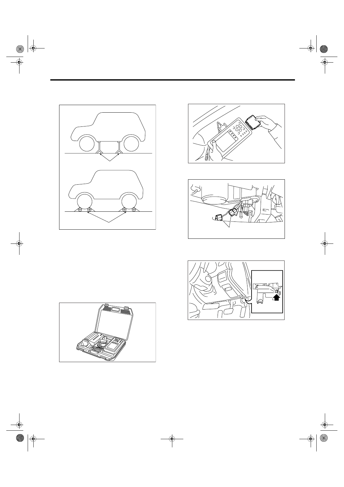
2) Lift-up the vehicle using a garage jack and place
it on rigid racks, or drive the vehicle onto free roll-
ers.
WARNING:
• Before lifting-up the vehicle, ensure parking
brakes are applied.
• Do not use a pantograph jack in place of a rig-
id rack.
• Secure a rope or wire to the front or rear tow-
ing hooks to prevent the lateral runout of front
wheels.
• Do not abruptly depress/release clutch pedal
or accelerator pedal during works even when
the engine is operating at low speeds since this
may cause vehicle to jump off free rollers.
• In order to prevent the vehicle from slipping
due to vibration, do not place any wooden
blocks or similar items between the rigid racks
and vehicle.
P0851
Park/Neutral Switch Input Circuit Low
P0852
Park/Neutral Switch Input Circuit High
P1160
Return Spring Failure
P1518
Starter Switch Circuit Low Input
P1560
Back-up Voltage Circuit Malfunction
P1570
Antenna
P1571
Reference Code Incompatibility
P1572
IMM Circuit Failure (Except Antenna Circuit)
P1574
Key Communication Failure
P1576
EGI Control Module EEPROM
P1577
IMM Control Module EEPROM
P1578
Meter Failure
P2088
Intake Camshaft Position Actuator Control Circuit Low (Bank 1)
P2089
Intake Camshaft Position Actuator Control Circuit High (Bank 1)
P2090
Exhaust Camshaft Position Actuator Control Circuit Low (Bank 1)
P2091
Exhaust Camshaft Position Actuator Control Circuit High (Bank 1)
P2092
Intake Camshaft Position Actuator Control Circuit Low (Bank 2)
P2093
Intake Camshaft Position Actuator Control Circuit High (Bank 2)
P2094
Exhaust Camshaft Position Actuator Control Circuit Low (Bank 2)
P2095
Exhaust Camshaft Position Actuator Control Circuit High (Bank 2)
P2101
Throttle Actuator Control Motor Circuit Range/Performance
P2102
Throttle Actuator Control Motor Circuit Low
P2103
Throttle Actuator Control Motor Circuit High
P2109
Throttle/Pedal Position Sensor “A” Minimum Stop Performance
P2122
Throttle/Pedal Position Sensor/Switch “D” Circuit Low Input
P2123
Throttle/Pedal Position Sensor/Switch “D” Circuit High Input
P2127
Throttle/Pedal Position Sensor/Switch “E” Circuit Low Input
P2128
Throttle/Pedal Position Sensor/Switch “E” Circuit High Input
P2135
Throttle/Pedal Position Sensor/Switch “A” / “B” Voltage Correlation
P2138
Throttle/Pedal Position Sensor/Switch “D” / “E” Voltage Correlation
P2228
Barometric Pressure Sensor Circuit Low
P2229
Barometric Pressure Sensor Circuit High
DTC
Item
EN(H4DOTC)(diag)-32
ENGINE (DIAGNOSTICS)
Inspection Mode
• Since the rear wheels will also rotate, do not
place anything near them. Also, make sure that
nobody goes in front of the vehicle.
2. SUBARU SELECT MONITOR
1) After clearing the memory, check for any remain-
ing unresolved trouble data. <Ref. to
EN(H4DOTC)(diag)-37, Clear Memory Mode.>
2) Idle the engine.
3) Prepare the Subaru Select Monitor kit. <Ref. to
EN(H4DOTC)(diag)-7, PREPARATION TOOL,
General Description.>
4) Connect the diagnosis cable to Subaru Select
Monitor.
5) Insert the cartridge to Subaru Select Monitor.
<Ref. to EN(H4DOTC)(diag)-7, PREPARATION
TOOL, General Description.>
6) Connect the test mode connector (A) located at
the lower portion of glove box.
7) Connect the Subaru Select Monitor to data link
connector located in the lower portion of the instru-
ment panel (on the driver’s side).
CAUTION:
Do not connect any scan tools except Subaru
Select Monitor or general scan tool.
(A) Rigid racks
(B) Free rollers
EN-00041
(A)
(B)
EN-00038
EN-00039
(A)
EN-01983
EN-02097
Нет комментариевНе стесняйтесь поделиться с нами вашим ценным мнением.
Текст