Subaru Legacy (2005 year). Service manual — part 314
EN(H4DOTC)(diag)-25
ENGINE (DIAGNOSTICS)
Subaru Select Monitor
4. READ CURRENT DATA FOR ENGINE. (NORMAL MODE)
1) On the «Main Menu» display screen, select the {Each System Check} and press the [YES] key.
2) On the «System Selection Menu» display screen, select the {Engine} and press the [YES] key.
3) Press the [YES] key after the information of engine type has been displayed.
4) On the «Engine Diagnosis» display screen, select the {Current Data Display & Save}, and then press the
[YES] key.
5) On the «Data Display Menu» screen, select the {Data Display} and press the [YES] key.
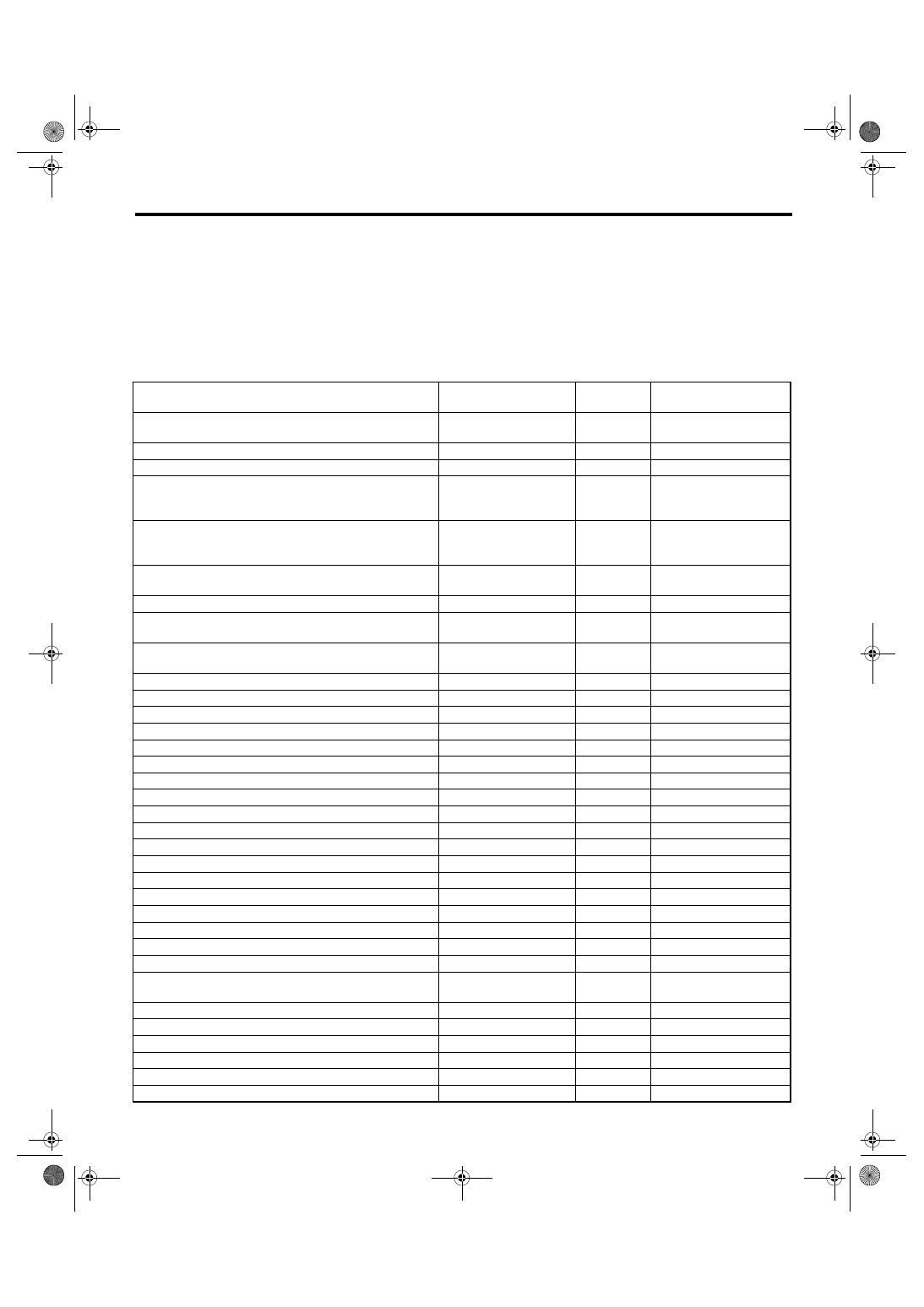
6) Using the scroll key, move the display screen up or down until the desired data is shown.
• A list of the support data is shown in the following table.
Remarks
Display
Unit of mea-
sure
Note (at idling)
Engine coolant temperature signal
Coolant Temp.
°C or °F
80 — 100
°C or 176 —
211
°F
A/F correction 1
A/F Correction #1
%
−10 — +10%
A/F learning 1
A/F Learning #1
%
−15 — +15%
Intake manifold absolute pressure
Mani. Absolute Pressure
mmHg, kPa,
inHg or psig
220 — 275 mmHg, 29.3
— 36.7 kPa, 8.7 — 10.8
inHg or 4.2 — 5.2 psig
Engine speed signal
Engine Speed
rpm
630 — 770 rpm (Agree
with the tachometer indi-
cation)
Vehicle speed signal
Vehicle Speed
km/h or
MPH
0 km/h or 0 MPH (at park-
ing)
Ignition timing signal
Ignition Timing
deg
10 — 15 deg
Intake air temperature signal
Intake Air Temp.
°C or °F
20 — 50
°C or 68 —
122
°F
Amount of intake air
Mass Air Flow
g/s or lb/m
2.1 — 3.1 g/s or 0.28 —
0.41 lb/m
Throttle opening angle signal
Throttle Opening Angle
%
2.0 — 2.4%
Rear oxygen sensor voltage
Rear O2 Sensor
V
0 — 1.0 V
Battery voltage
Battery Voltage
V
12 — 15 V
Mass air flow voltage
Air Flow Sensor Voltage
V
1.0 — 1.7 V
Injection 1 pulse width
Fuel Injection #1 Pulse
ms
1.2 — 2.2 ms
Knock sensor correction
Knocking Correction
deg
0.0 deg
Acceleration opening angle signal
Accel. Opening Angle
%
0.0%
Primary supercharged pressure control signal
Primary Control
%
0.0%
Purge control solenoid duty ratio
CPC Valve Duty Ratio
%
0 — 25%
Generator duty ratio
ALT Duty
%
0 — 100%
Fuel pump duty ratio
Fuel Pump Duty
%
30 — 40%
AVCS advance angle amount RH
VVT Adv. Ang. Amount R
deg
±5 deg
AVCS advance angle amount LH
VVT Adv. Ang. Amount L
deg
±5 deg
Oil flow control solenoid valve duty RH (AVCS)
OCV duty R
%
0 — 20%
Oil flow control solenoid valve duty LH (AVCS)
OCV duty L
%
0 — 20%
Oil flow control solenoid valve current RH
OCV Current R
mA
40 — 100 mA
Oil flow control solenoid valve current LH
OCV Current L
mA
40 — 100 mA
A/F sensor current value 1
A/F Sensor #1 Current
mA
−20 — 20 mA
A/F sensor resistance value 1
A/F Sensor #1 Resis-
tance
Ω
27 — 35 mA
A/F sensor output lambda 1
A/F Sensor #1
—
1.0
A/F correction 3
A/F Correction #3
%
0.00%
Throttle motor duty
Throttle Motor Duty
%
−5%
Throttle power supply voltage
Throttle Motor Voltage
V
12 — 15 V
Sub throttle sensor voltage
Sub-Throttle Sensor
V
1.5 V
Main throttle sensor voltage
Main-throttle Sensor
V
0.6 V
EN(H4DOTC)(diag)-26
ENGINE (DIAGNOSTICS)
Subaru Select Monitor
NOTE:
For detailed operation procedure, refer to the SUBARU SELECT MONITOR OPERATION MANUAL.
5. READ CURRENT DATA FOR ENGINE (OBD MODE)
1) On the «Main Menu» display screen, select the {Each System Check} and press the [YES] key.
2) On the «System Selection Menu» display screen, select the {Engine} and press the [YES] key.
3) Press the [YES] key after the information of engine type has been displayed.
4) On the «Engine Diagnosis» display screen, select the {OBD System} and press the [YES] key.
5) On the «OBD Menu» display screen, select the {Current Data Display & Save}, and then press the [YES]
key.
6) On the «Data Display Menu» screen, select the {Data Display} and press the [YES] key.
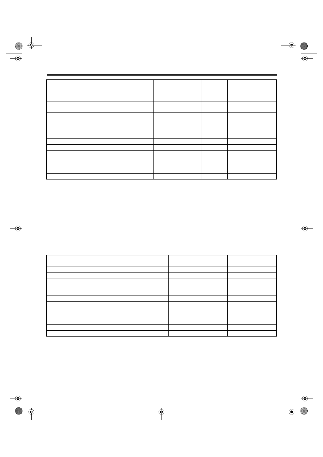
7) Using the scroll key, move the display screen up or down until the desired data is shown.
• A list of the support data is shown in the following table.
NOTE:
For detailed operation procedure, refer to the SUBARU SELECT MONITOR OPERATION MANUAL.
Sub acceleration sensor voltage
Sub-Accelerator Sensor
V
1.1 V
Main acceleration sensor voltage
Main-Accelerator Sensor
V
1.0 V
Atmospheric pressure
Atmosphere Pressure
mmHg, kPa,
inHg or psig
—
Intake manifold relative pressure
Mani. Relative Pressure
mmHg, kPa,
inHg or psig
Intake manifold absolute
pressure — Atmospheric
pressure
Memory vehicle speed
Memorized Cruise
Speed
km/h or
MPH
—
Estimated cumulative driving distance
Odd Meter
km or miles
—
Exhaust AVCS retard angle amount RH
Exh. VVT Retard Ang. R
deg
±5 deg
Exhaust AVCS retard angle amount LH
Exh. VVT Retard Ang. L
deg
±5 deg
Exhaust oil flow control solenoid valve duty ratio RH
Exh. OCV Duty R
%
0 — 20%
Exhaust oil flow control solenoid valve duty ratio LH
Exh. OCV Duty L
%
0 — 20%
Exhaust oil flow control solenoid valve current value RH
Exh. OCV Current R
mA
40 — 100 mA
Exhaust oil flow control solenoid valve current value LH
Exh. OCV Current L
mA
40 — 100 mA
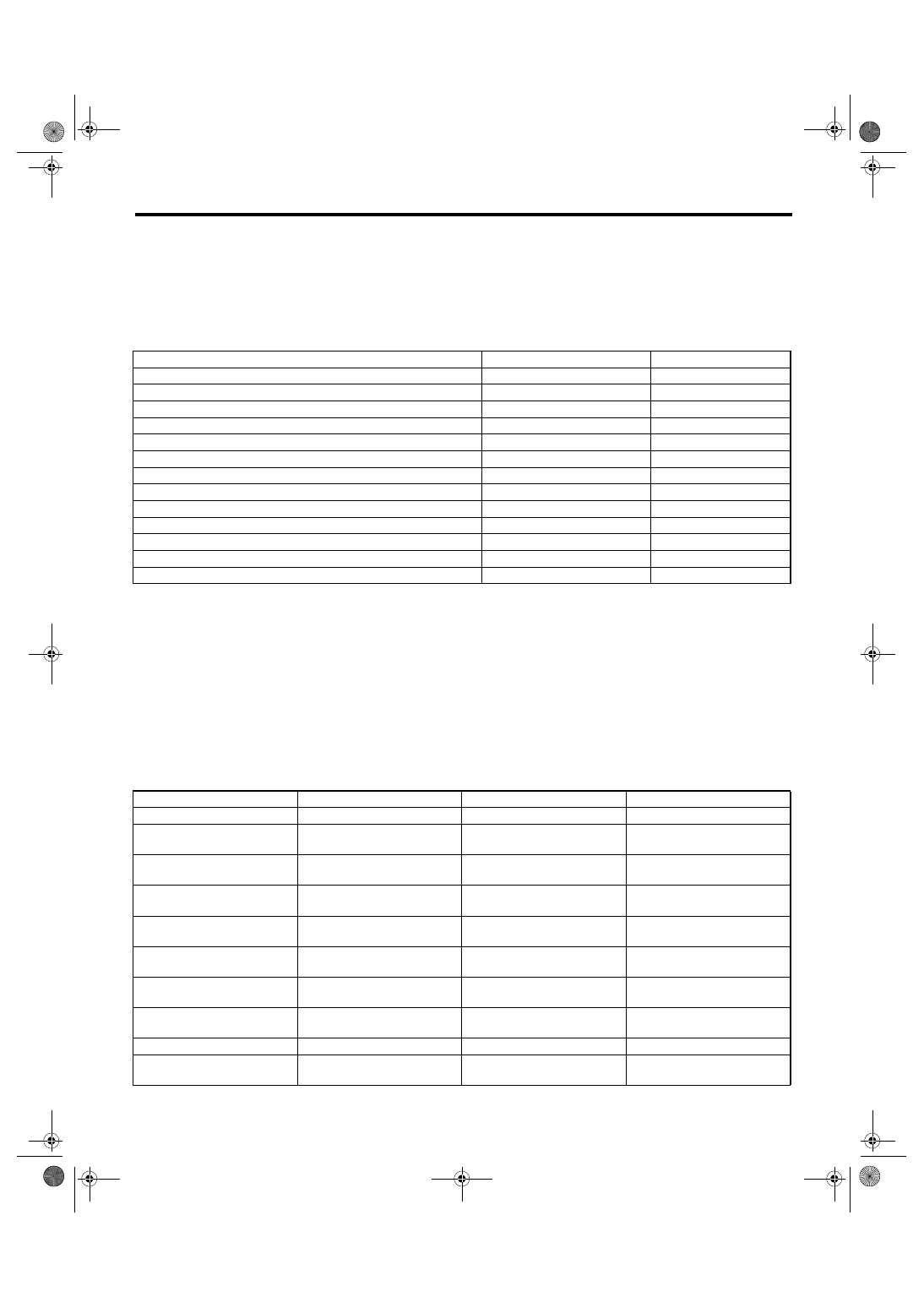
Description
Display
Unit of measure
Number of diagnosis code
Number of Diag. Code:
—
Condition of malfunction indicator light
MI (MIL)
ON or OFF
Monitoring test of misfire
Misfire monitoring
no support
Monitoring test of fuel system
Fuel system monitoring
complete or incomplete
Monitoring test of comprehensive component
Component monitoring
complete or incomplete
Test of catalyst
Catalyst Diagnosis
no support
Test of heating-type catalyst
Heated catalyst
no support
Test of evaporative emission purge control system
Evaporative purge system
no support
Test of secondary air system
Secondary air system
no support
Test of air conditioning system refrigerant
A/C system refrigerant
no support
Test of oxygen sensor
Oxygen sensor
complete or incomplete
Test of oxygen sensor heater
O2 Heater Diagnosis
complete or incomplete
Test of EGR system
EGR system
no support
Remarks
Display
Unit of mea-
sure
Note (at idling)
EN(H4DOTC)(diag)-27
ENGINE (DIAGNOSTICS)
Subaru Select Monitor
6. READ FREEZE FRAME DATA FOR ENGINE. (OBD MODE)
1) On the «Main Menu» display screen, select the {Each System Check} and press the [YES] key.
2) On the «System Selection Menu» display screen, select the {Engine} and press the [YES] key.
3) Press the [YES] key after the information of engine type has been displayed.
4) On the «Engine Diagnosis» display screen, select the {OBD System} and press the [YES] key.
5) On the «OBD Menu» display screen, select the {Freeze Frame Data} and press the [YES] key.
• A list of the support data is shown in the following table.
NOTE:
For detailed operation procedure, refer to the SUBARU SELECT MONITOR OPERATION MANUAL.
7. LED OPERATION MODE FOR ENGINE
1) On the «Main Menu» display screen, select the {Each System Check} and press the [YES] key.
2) On the «System Selection Menu» display screen, select the {Engine} and press the [YES] key.
3) Press the [YES] key after the information of engine type has been displayed.
4) On the «Engine Diagnosis» display screen, select the {Current Data Display & Save}, and then press the
[YES] key.
5) On the «Data Display» screen, select the {Data & LED Display} and press the [YES] key.
6) Using the scroll key, move the display screen up or down until the desired data is shown.
• A list of the support data is shown in the following table.
Description
Display
Unit of measure
DTC for freeze frame data
Freeze frame data
DTC
Air fuel ratio control system for bank 1
Fuel system for Bank1
ON or OFF
Engine load data
Engine Load
%
Engine coolant temperature signal
Coolant Temp.
°C or °F
Short term fuel trim by front oxygen (A/F) sensor
Short term fuel trim B1
%
Long term fuel trim by front oxygen (A/F) sensor
Long term fuel trim B1
%
Intake manifold absolute pressure signal
Mani. Absolute Pressure
mmHg, kPa, inHg or psig
Engine speed signal
Engine Speed
rpm
Vehicle speed signal
Vehicle Speed
km/h or MPH
Ignition timing signal
Ignition Timing
°
Amount of intake air
Mass Air Flow
g/s or lb/m
Intake air temperature signal
Intake Air Temp
°C or °F
Throttle position signal
Throttle Opening Angle
%
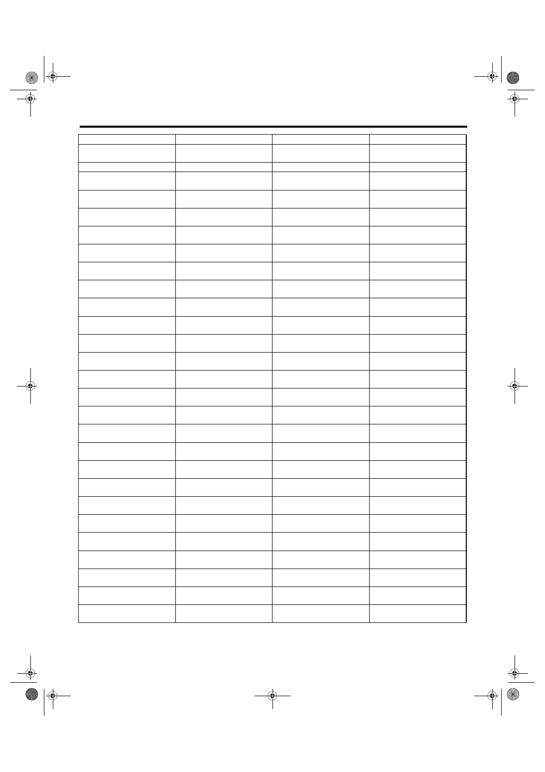
Remarks
Display
Message
LED “ON” requirements
AT/MT identification signal
AT Vehicle ID Signal
ON or OFF
Illuminate (AT model)
Test mode signal
Test Mode Signal
ON or OFF
When test mode connector is
connected.
Clear memory signal
Clear Memory Terminal
ON or OFF
Clear memory connector is
connected.
Neutral position switch signal
Neutral Position Switch
ON or OFF
When neutral position signal is
entered.
Idle switch signal
Idle Switch Signal
ON or OFF
When idle switch signal is
entered.
Ignition switch signal
Ignition Switch
ON or OFF
When ignition switch is turned
ON.
Power steering switch signal
P/S Switch
ON or OFF
When power steering switch is
entered.
Steering wheel switch signal
Handle Switch
RHD or LHD
When handle switch signal is
input.
Starter switch signal
Starter Switch
ON or OFF
When starter switch is input.
Air conditioning switch signal
A/C Switch
ON or OFF
When air conditioning switch is
input.
EN(H4DOTC)(diag)-28
ENGINE (DIAGNOSTICS)
Subaru Select Monitor
NOTE:
For detailed operation procedure, refer to the SUBARU SELECT MONITOR OPERATION MANUAL.
Rear oxygen sensor rich sig-
nal
Rear O2 Rich Signal
ON or OFF
When rear oxygen sensor mix-
ture ratio is rich.
Knocking signal
Knocking Signal
ON or OFF
When knocking signal is input.
Crankshaft position sensor
signal
Crankshaft Position Signal
ON or OFF
When crankshaft position sen-
sor signal is input.
Camshaft position sensor sig-
nal
Camshaft Position Signal
ON or OFF
When camshaft position sen-
sor signal is entered.
Rear defogger switch signal
Rear Defogger Switch
ON or OFF
When rear defogger switch is
turned ON.
Blower fan switch signal
Blower Fan SW
ON or OFF
When blower fan switch is
turned ON.
Small light switch signal
Light Switch
ON or OFF
When small light switch is
turned ON.
Windshield wiper switch signal
Wiper Switch
ON or OFF
When windshield wiper switch
is turned ON.
A/C middle pressure switch
signal
A/C Mid Pressure Switch
ON or OFF
When A/C middle pressure
switch is turned ON.
Air conditioning relay signal
A/C Compressor Signal
ON or OFF
When air conditioning relay is
in function.
Radiator fan relay 1 signal
Radiator Fan Relay #1
ON or OFF
When radiator fan relay 1 is in
function.
Radiator fan relay 2 signal
Radiator Fan Relay #2
ON or OFF
When radiator fan relay 2 is in
function.
AT retard angle demand signal Retard Signal
ON or OFF
When AT retard angle demand
signal is input.
AT fuel cut signal
Fuel Cut
ON or OFF
When AT fuel cut signal is
input.
Torque down output signal
Ban of Torque Down
ON or OFF
When torque down output sig-
nal is input.
Torque down demand signal
Request Torque Down
ON or OFF
When torque down demand
signal is input.
AT coordinate permission sig-
nal
Torque Permission Signal
ON or OFF
When AT coordinate permis-
sion signal is input.
Electronic throttle control
motor relay signal
ETC Motor Relay
ON or OFF
When electronic throttle con-
trol motor relay is in function.
Clutch switch signal
Clutch Switch
ON or OFF
When clutch switch is turned
to ON.
Stop light switch signal
Stop Light Switch
ON or OFF
When stop switch is turned to
ON.
SET/COAST switch signal
SET/CST Switch
ON or OFF
When SET/CST switch is
turned to ON.
RESUME/ACCEL switch sig-
nal
RES/ACC Switch
ON or OFF
When RES/ACC switch is
turned to ON.
Brake switch signal
Brake Switch
ON or OFF
When brake switch is turned to
ON.
Main switch signal
Main Switch
ON or OFF
When main switch is turned to
ON.
Cancel switch signal
Cancel Switch
ON or OFF
When cancel switch is turned
to ON.
Data reception signal
Body Int. Unit Data
ON or OFF
When data reception signal is
entered.
Counter update signal
Body Int. Unit Count
ON or OFF
When counter update signal is
entered.
Remarks
Display
Message
LED “ON” requirements
Нет комментариевНе стесняйтесь поделиться с нами вашим ценным мнением.
Текст