Subaru Legacy (2005 year). Service manual — part 540
4AT-141
AUTOMATIC TRANSMISSION
AT Main Case
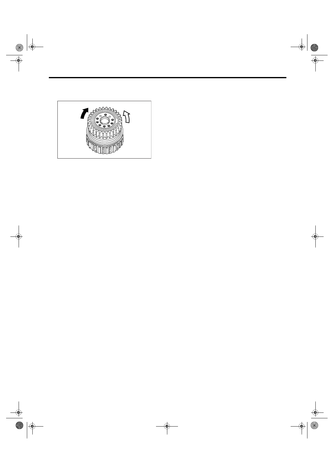
3) Set the inner race. Make sure that the clutch
locks in the clockwise direction and rotates in the
counterclockwise direction.
E: INSPECTION
1. HIGH CLUTCH AND REVERSE CLUTCH
Check the following items.
• Drive plate facing for wear or damage
• Driven plate for discoloration (burned color)
• Snap ring for wear, return spring for setting and
breakage, and snap ring retainer for deformation
• Lip seal and D-ring for damage
• Piston and drum check ball for operation
• Adjust total end play. <Ref. to 4AT-108, AD-
JUSTMENT, Oil Pump Housing.>
2. PLANETARY GEAR AND LOW CLUTCH
Check the following items.
• Drive plate facing for wear or damage
• Driven plate for discoloration (burned color)
• Snap ring for wear, return spring for setting and
breakage, and spring retainer for deformation
• Lip seal and D-ring for damage
• Piston check ball for operation
• Measure the total end play and adjust it within
specification. <Ref. to 4AT-108, ADJUSTMENT,
Oil Pump Housing.>
3. 2-4 BRAKE
Check the following items.
• Drive plate facing for wear or damage
• Driven plate for discoloration (burned color)
• Snap ring for wear and spring retainer for defor-
mation
• Lip seal and D-ring for damage
• Measure the total end play and adjust it within
specification. <Ref. to 4AT-108, ADJUSTMENT,
Oil Pump Housing.>
4. ONE-WAY CLUTCH
• Check the snap ring is not worn and the seal
rings are not deformed.
• Measure the total end play and adjust it within
specification. <Ref. to 4AT-108, ADJUSTMENT,
Oil Pump Housing.>
5. LOW & REVERSE BRAKE
Check the following items.
• Drive plate facing for wear or damage
• Driven plate for discoloration (burned color)
• Snap ring for wear and spring retainer for defor-
mation
(A) Lock
(B) Rotate
AT-00282
(B)
(A)
4AT-142
AUTOMATIC TRANSMISSION
Transmission Control Device
42.Transmission Control Device
A: REMOVAL
1) Remove the transmission assembly from vehi-
cle. <Ref. to 4AT-39, REMOVAL, Automatic Trans-
mission Assembly.>
2) Pull out the torque converter clutch assembly.
<Ref. to 4AT-81, REMOVAL, Torque Converter
Clutch Assembly.>
3) Remove the input shaft.
4) Lift up the lever on rear part of transmission har-
ness connector, and then remove it from stay.
5) Disconnect the air breather hose. <Ref. to 4AT-
79, REMOVAL, Air Breather Hose.>
6) Remove the inhibitor switch connector from stay.
7) Wrap vinyl tape around the nipple attached to
the air breather hose.
8) Remove the pitching stopper bracket.
9) Remove the inhibitor switch.
10) Remove the control valve body assembly.
<Ref. to 4AT-62, REMOVAL, Control Valve Body.>
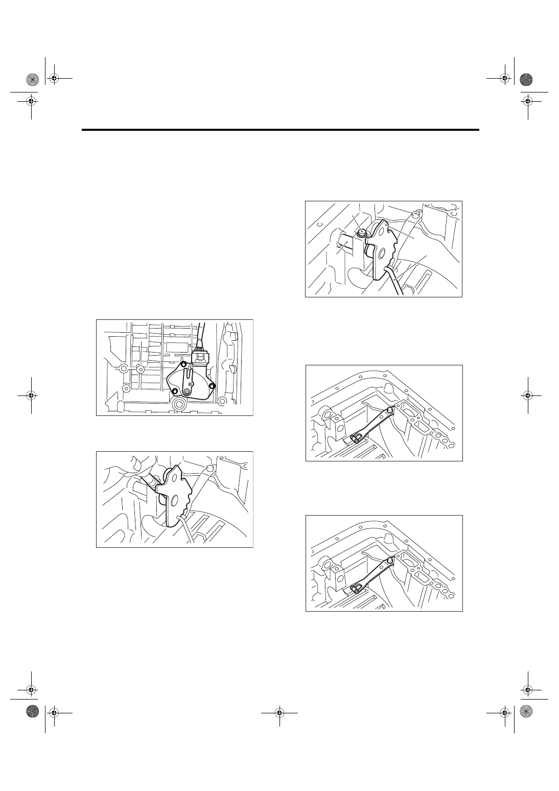
11) Pull out the straight pin of manual plate.
12) Remove the bolts securing select lever, and
then remove the select lever, manual plate and
parking rod.
NOTE:
Be careful not to damage the lips of press-fitted oil
seal in the case.
13) Remove the detention spring.
B: INSTALLATION
1) Install the detention spring to transmission case.
Tightening torque:
6 N
⋅
m (0.6 kgf-m, 4 ft-lb)
AT-00304
AT-02224
(A) Bolt
(B) Range select lever
(C) Manual plate
(D) Parking rod
AT-02225
(A)
(B)
(C)
(D)
AT-00307
AT-00307
4AT-143
AUTOMATIC TRANSMISSION
Transmission Control Device
2) Insert the select lever, and then tighten the bolt.
Tightening torque:
6 N
⋅
m (0.6 kgf-m, 4 ft-lb)
3) Insert the manual plate and parking rod.
4) Insert the straight pin to manual plate.
5) Install the oil pan and control valve assembly.
<Ref. to 4AT-63, INSTALLATION, Control Valve
Body.>
6) Turn over the transmission case to its original
position.
7) Install the pitching stopper bracket.
Tightening torque:
41 N
⋅
m (4.2 kgf-m, 30.4 ft-lb)
8) Install and adjust the inhibitor switch. <Ref. to
4AT-51, Inhibitor Switch.>
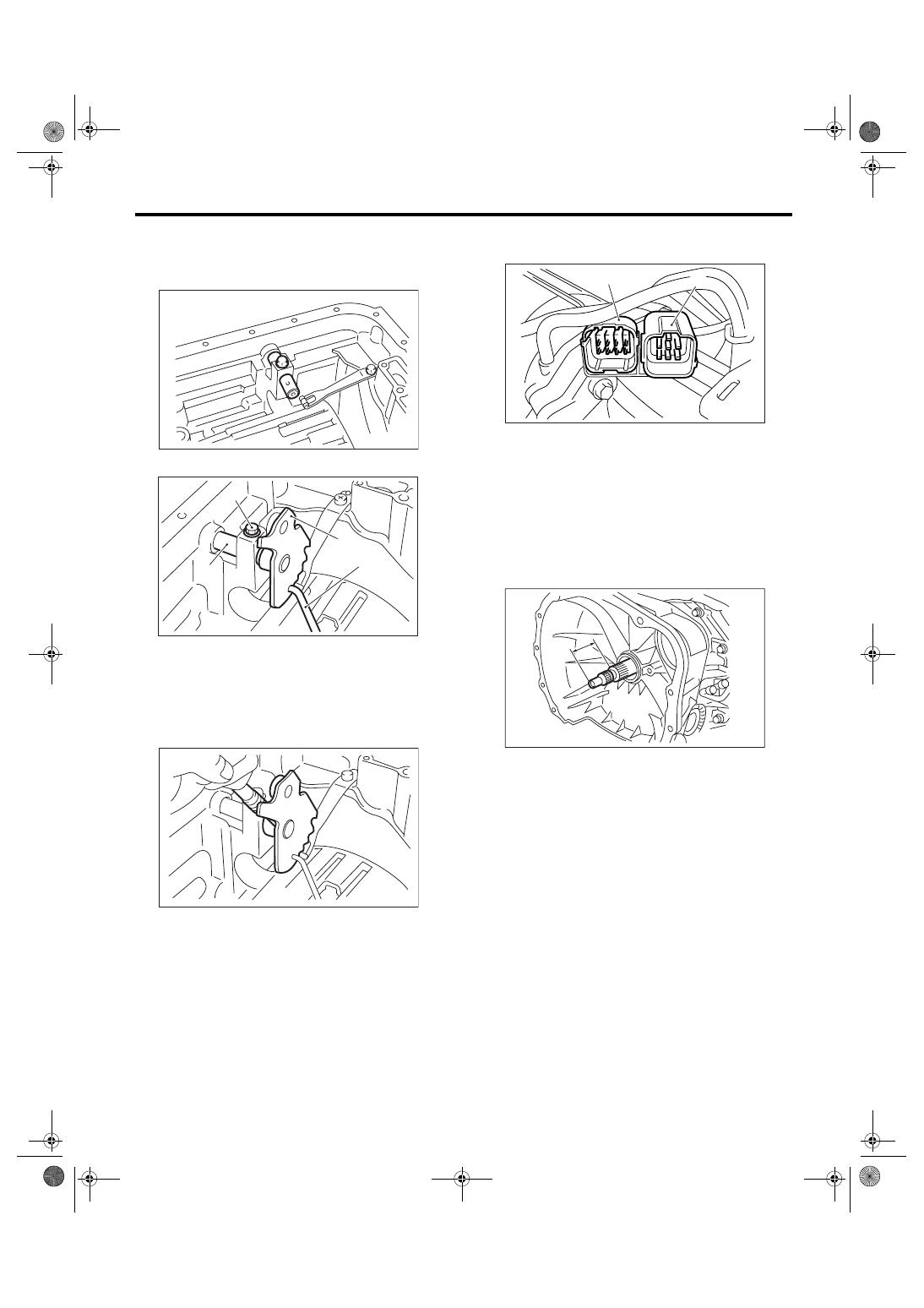
9) Insert the inhibitor switch and transmission con-
nector to stay.
10) Install the air breather hose. <Ref. to 4AT-79,
INSTALLATION, Air Breather Hose.>
11) Insert the input shaft while rotating it lightly by
hand, and then check the protrusion amount.
Normal protrusion A:
50 — 55 mm (1.97 — 2.17 in)
12) Install the torque converter clutch assembly.
<Ref. to 4AT-81, INSTALLATION, Torque Convert-
er Clutch Assembly.>
13) Install the transmission assembly into vehicle.
<Ref. to 4AT-42, INSTALLATION, Automatic
Transmission Assembly.>
C: INSPECTION
Check the manual lever and detention spring are
not worn or otherwise damaged.
(A) Bolt
(B) Range select lever
(C) Manual plate
(D) Parking rod
AT-00308
AT-02225
(A)
(B)
(C)
(D)
AT-02224
(A) Transmission connector
(B) Inhibitor switch connector
AT-01351
(B)
(A)
AT-03204
A
4AT-144
AUTOMATIC TRANSMISSION
Transmission Control Device
Нет комментариевНе стесняйтесь поделиться с нами вашим ценным мнением.
Текст