Subaru Legacy (2005 year). Service manual — part 538

4AT-133
AUTOMATIC TRANSMISSION
AT Main Case
2) Remove the needle bearing after taking out the
snap ring.
D: ASSEMBLY
1. HIGH CLUTCH AND REVERSE CLUTCH
1) Install the seal ring and lip seal to the high clutch
piston and reverse clutch piston.
2) Install the high clutch piston to reverse clutch
piston.
3) Install the reverse clutch piston to high clutch
drum. Align the groove on reverse clutch piston
with the groove on high clutch drum during installa-
tion.
4) Install the spring retainer to high clutch piston.
5) Install the ST to high clutch piston.
ST
498437000
HIGH CLUTCH PISTON
GUIDE
6) Install the cover to high clutch piston in order to
prevent the high clutch piston seal from folding.
7) Install the snap ring using ST1 and ST2.
ST1
398673600
COMPRESSOR
ST2
498627100
SEAT
ST3
498437000
HIGH CLUTCH PISTON
GUIDE
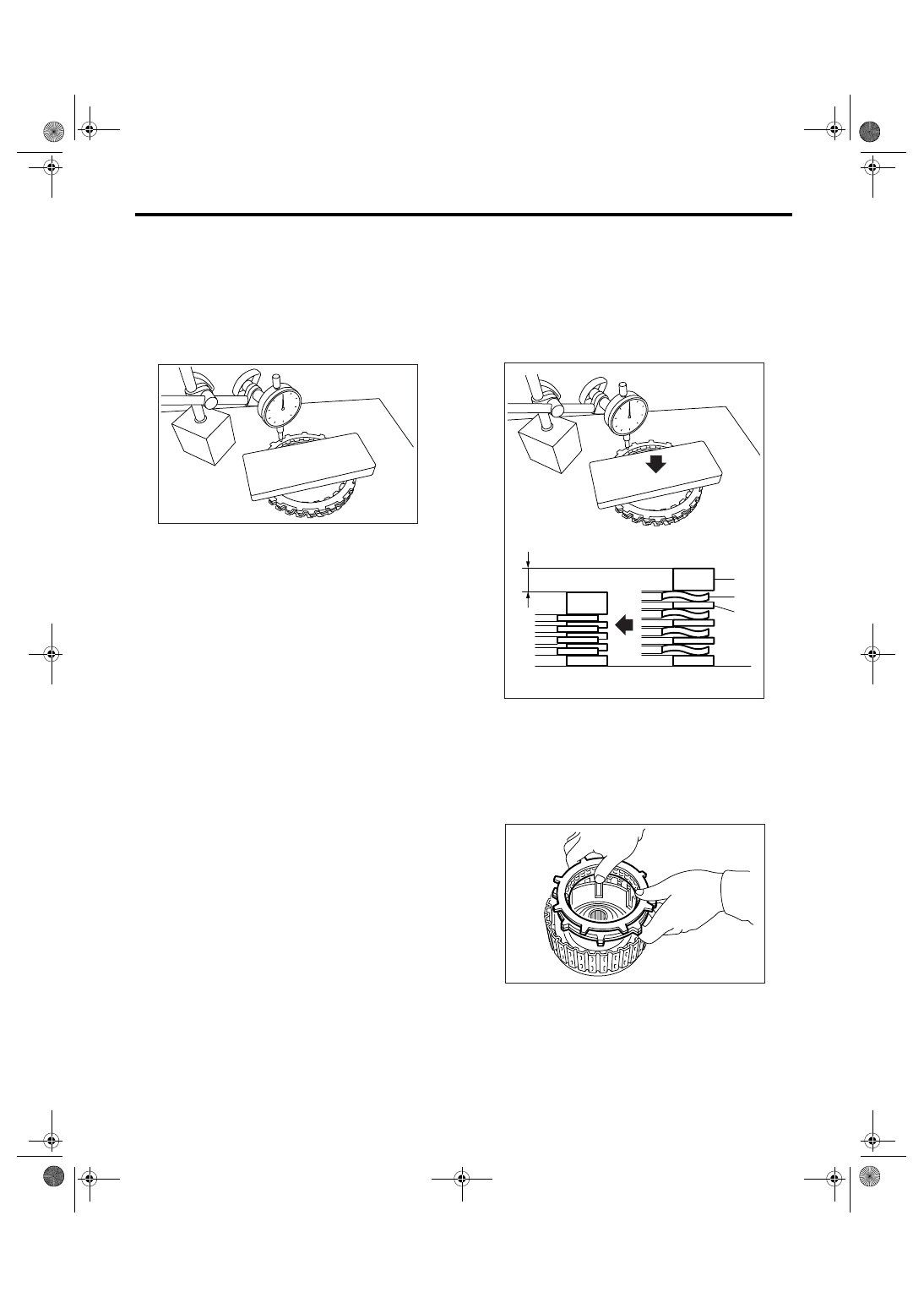
8) Place the dish plate, driven plate, drive plate and
retaining plate neatly in this order on surface table.
9) Set the dial gauge to clutch, and read its scale.
NOTE:
The value, which is read in the gauge at this time, is
zero point.
(A) Needle bearing
(B) Snap ring
(A) High clutch piston
(B) Reverse clutch piston
(A) Reverse clutch piston
(B) High clutch drum
AT-00268
(B)
(A)
AT-00240
(A)
(B)
AT-00241
(A)
(B)
(A) Spring retainer
(B) High clutch drum
AT-00242
(B)
(A)
AT-00243
ST
AT-00244
ST1
ST3
ST2
4AT-134
AUTOMATIC TRANSMISSION
AT Main Case
10) Scale and record the weight “Z” of a flat board
which will be put on retaining plate.
NOTE:
• Use a stiff board which does not bend against
load as a flat board to be put on retaining plate.
• Use a flat board of its weight less than 25.5 kg
(56.2 lb).
11) Put the flat board weighed on retaining plate.
12) Using the following formula, calculate “N” indi-
cated on the push/pull gauge.
N = 250 N (25.5 kgf, 56.2 lbf)
− Z
N: Value indicated on push/pull gauge
250 N (25.5 kgf, 56.2 lbf): Load applied to clutch
plate
Z: Flat board weight
13) Press the center of retaining plate by applying a
force of N using push/pull gauge, and then mea-
sure and record the height A. Measure at three
places or more in even distance and take the aver-
age value.
NOTE:
If three places, measure in every 120
°. If four plac-
es, measure in every 90
°.
14) Install the thickest driven plate to piston side,
and then install the driven plate, drive plate, retain-
ing plate to high clutch drum.
15) Install the snap ring to high clutch drum.
AT-01720
(A) Driven plate
(B) Drive plate
(C) Retaining plate
AT-01725
(C)
(B)
(A)
A
AT-00245
4AT-135
AUTOMATIC TRANSMISSION
AT Main Case
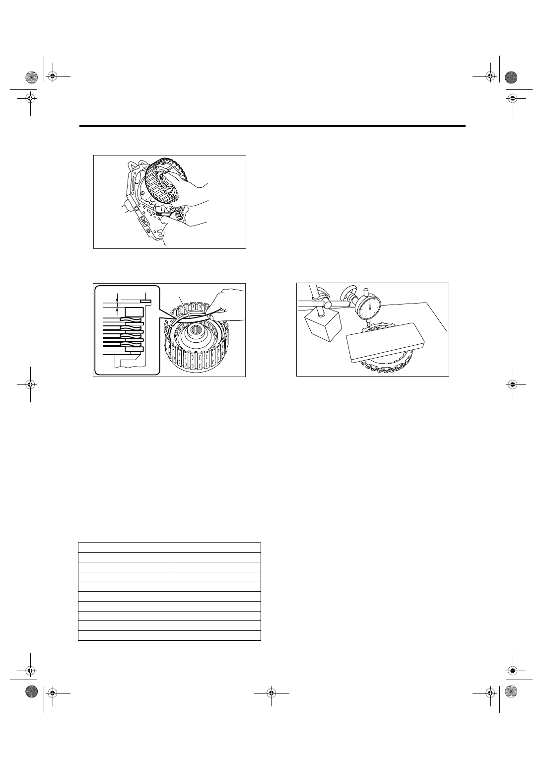
16) Apply compressed air intermittently to check for
operation.
17) Measure the clearance B between retaining
plate and snap ring. (High clutch)
At this time, do not press down the retaining plate.
18) Piston stroke calculation
Select the retaining plate within the specification by
calculating with A and B dimensions recorded be-
fore. If the calculated value exceeds the service
limit, replace the drive plate with a new one and ad-
just it within the specification.
T = A + B
T: Piston stroke
A: Collapse amount of drive plate
B: Clearance between retaining plate and snap ring
Initial specification:
2.0 — 2.3 mm (0.079 — 0.091 in)
Service limit:
2.6 mm (0.102 in)
19) Place the dish plate, driven plate, drive plate
and retaining plate neatly in this order on surface
table.
20) Set the dial gauge to clutch, and read its scale.
NOTE:
The value, which is read in the gauge at this time, is
zero point.
21) Scale and record the weight “Z” of a flat board
which will be put on retaining plate.
NOTE:
• Use a stiff board which does not bend against
load as a flat board to be put on retaining plate.
• Use a flat board of its weight less than 15.3 kg
(33.7 lb).
22) Put the flat board weighed on retaining plate.
23) Using the following formula, calculate “N” indi-
cated on the push/pull gauge.
N = 150 N (15.3 kgf, 33.7 lbf)
− Z
N: Value indicated on push/pull gauge
150 N (15.3 kgf, 33.7 lbf): Load applied to clutch
plate
Z: Flat board weight
(A) Thickness gauge
High clutch retaining plate
Part No.
Thickness mm (in)
31567AA670
5.1 (0.201)
31567AA680
5.2 (0.205)
31567AA690
5.3 (0.209)
31567AA700
5.4 (0.213)
31567AA710
5.5 (0.217)
31567AA720
5.6 (0.220)
31567AA730
5.7 (0.224)
31567AA740
5.8 (0.228)
AT-00246
AT-01726
(A)
B
AT-01720
4AT-136
AUTOMATIC TRANSMISSION
AT Main Case
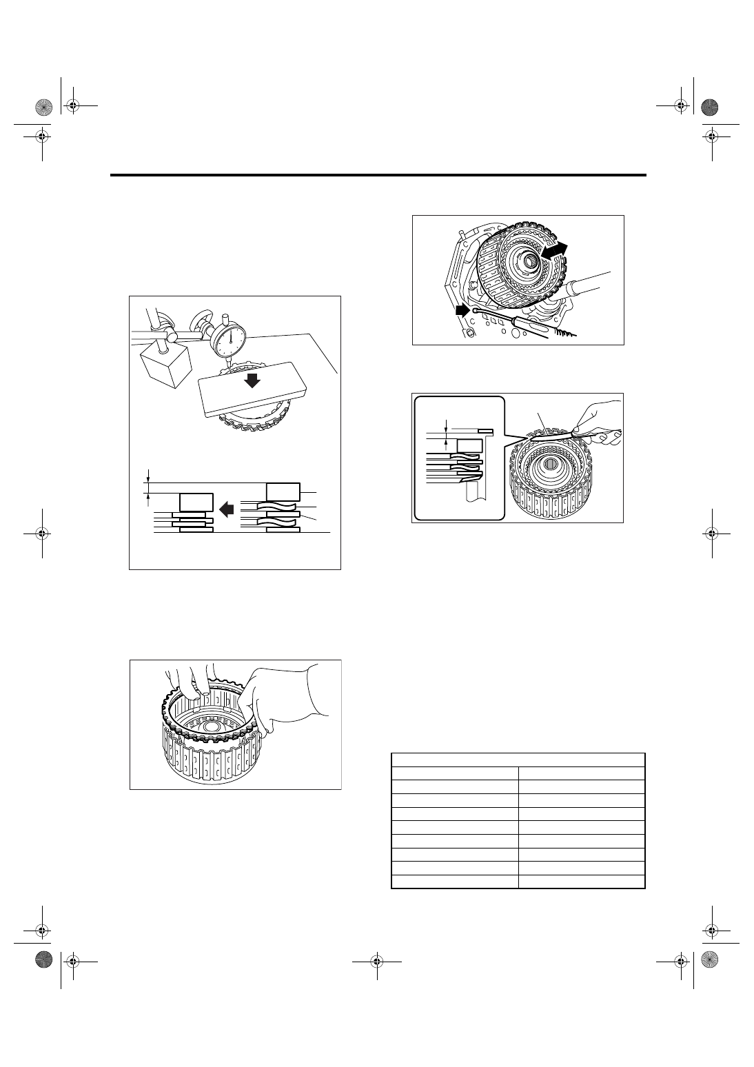
24) Press the center of retaining plate by applying a
force of N using push/pull gauge, and then mea-
sure and record the height A. Measure at three
places or more in even distance and take the aver-
age value.
NOTE:
If three places, measure in every 120
°. If four plac-
es, measure in every 90
°.
25) Install the driven plate, drive plate, retaining
plate and snap ring.
26) Apply compressed air intermittently to check for
operation.
27) Measure the clearance B between retaining
plate and snap ring. (Reverse clutch)
At this time, do not press down the retaining plate.
28) Piston stroke calculation
Select the retaining plate within the specification by
calculating with A and B dimensions recorded be-
fore. If the calculated value exceeds the service
limit, replace the drive plate with a new one and ad-
just it within the specification.
T = A + B
T: Piston stroke
A: Collapse amount of drive plate
B: Clearance between retaining plate and snap ring
Initial specification:
1.1 — 1.4 mm (0.043 — 0.055 in)
Service limit:
1.6 mm (0.063 in)
(A) Driven plate
(B) Drive plate
(C) Retaining plate
AT-01727
(C)
(B)
(A)
A
AT-00247
(A) Thickness gauge
Reverse clutch retaining plate
Part No.
Thickness mm (in)
31567AA910
4.0 (0.157)
31567AA920
4.2 (0.165)
31567AA930
4.4 (0.173)
31567AA940
4.6 (0.181)
31567AA950
4.8 (0.189)
31567AA960
5.0 (0.197)
31567AA970
5.2 (0.205)
31567AA980
5.4 (0.213)
AT-00248
AT-01728
(A)
B
Нет комментариевНе стесняйтесь поделиться с нами вашим ценным мнением.
Текст