Subaru Legacy (2005 year). Service manual — part 70
ME(H4SO 2.0)-63
MECHANICAL
Cylinder Head
5. VALVE SPRING
1) Check the valve springs for damage, free length,
and tension. Replace the valve spring if it is not
within the standard presented in the table.
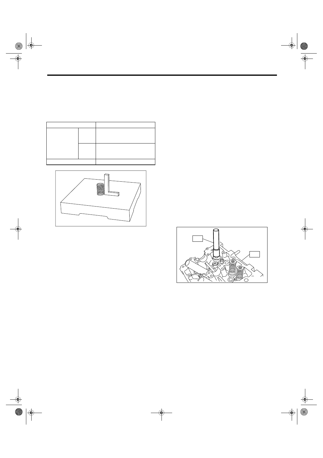
2) To measure the squareness of the valve spring,
stand the spring on a surface plate and measure its
deflection at the top of spring using a try square.
6. INTAKE AND EXHAUST VALVE OIL
SEAL
In the following case, pinch and remove the oil seal
from valve using pliers, and then replace it with a
new one.
• When the lip is damaged.
• When the spring is out of the specified position.
• When readjusting the surfaces of intake valve
and valve sheet.
• When replacing the intake valve guide.
1) Place the cylinder head on ST1.
2) Using ST2, press-fit the oil seal.
CAUTION:
• Apply engine oil to oil seal before press-fit-
ting.
• When press-fitting the oil seal, do not use a
hammer or strike in.
• Differentiate between the intake valve oil seal
and exhaust valve oil seal by noting their differ-
ence in color.
ST1
498267800
CYLINDER HEAD TABLE
ST2
498857100
VALVE OIL SEAL GUIDE
Color of rubber part:
Intake [Gray]
Exhaust [Green]
Free length
mm (in) 54.30 (2.1378)
Tension/spring
height
Set
214 — 246
(22 — 25, 48 — 55)/45.0
(1.772)
N (kgf, lbf)/mm
(in) Lift
526 — 582
(54 — 59, 119 — 130)/34.7
(1.366)
Squareness
2.5
°, 2.4 mm (0.094 in)
ME-00283
ME-00284
ST1
ST2
ME(H4SO 2.0)-64
MECHANICAL
Cylinder Block
21.Cylinder Block
A: REMOVAL
NOTE:
Before conducting this procedure, drain engine oil
completely.
1) Remove the intake manifold. <Ref. to FU(H4SO
2.0)-11, REMOVAL, Intake Manifold.>
2) Remove the V-belts. <Ref. to ME(H4SO 2.0)-37,
REMOVAL, V-belt.>
3) Remove the crank pulley. <Ref. to ME(H4SO
2.0)-40, REMOVAL, Crank Pulley.>
4) Remove the timing belt cover. <Ref. to
ME(H4SO 2.0)-42, REMOVAL, Timing Belt Cov-
er.>
5) Remove the timing belt. <Ref. to ME(H4SO 2.0)-
43, REMOVAL, Timing Belt.>
6) Remove the cam sprocket. <Ref. to ME(H4SO
2.0)-48, REMOVAL, Cam Sprocket.>
7) Remove the crank sprocket. <Ref. to ME(H4SO
2.0)-40, REMOVAL, Crank Pulley.>
8) Remove the generator and A/C compressor with
their brackets.
9) Remove the rocker cover.
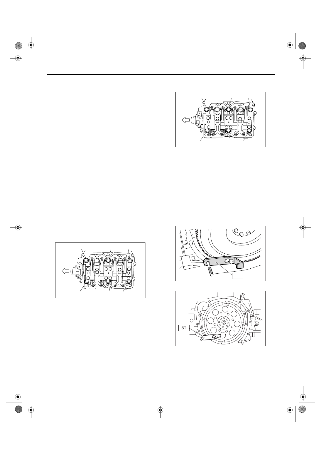
10) Remove the cylinder head bolts in alphabetical
sequence shown in the figure.
NOTE:
Leave the bolts (a) and (c) engaged by three or four
threads to prevent the cylinder head from falling.
11) While tapping the cylinder head with a plastic
hammer, separate it from cylinder block.
12) Remove the bolts (a) and (c) to remove the cyl-
inder head.
13) Remove the cylinder head gasket.
NOTE:
Do not scratch the mating surface of cylinder head
and cylinder block.
14) Similarly, remove the cylinder head RH.
15) Remove the clutch housing cover (MT model).
16) Remove the flywheel (MT model) or drive plate
(AT model).
Lock the crankshaft using ST.
ST
498497100
CRANKSHAFT STOPPER
• MT model
• AT model
17) Remove the oil separator cover.
18) Remove the water by-pass pipe for heater.
(A) Front side
ME-00296
(a)
(b)
(c)
(e)
(f)
(A)
(d)
(A) Front side
ME-00296
(a)
(b)
(c)
(e)
(f)
(A)
(d)
ME-00297
ST
ME-00298
ME(H4SO 2.0)-65
MECHANICAL
Cylinder Block
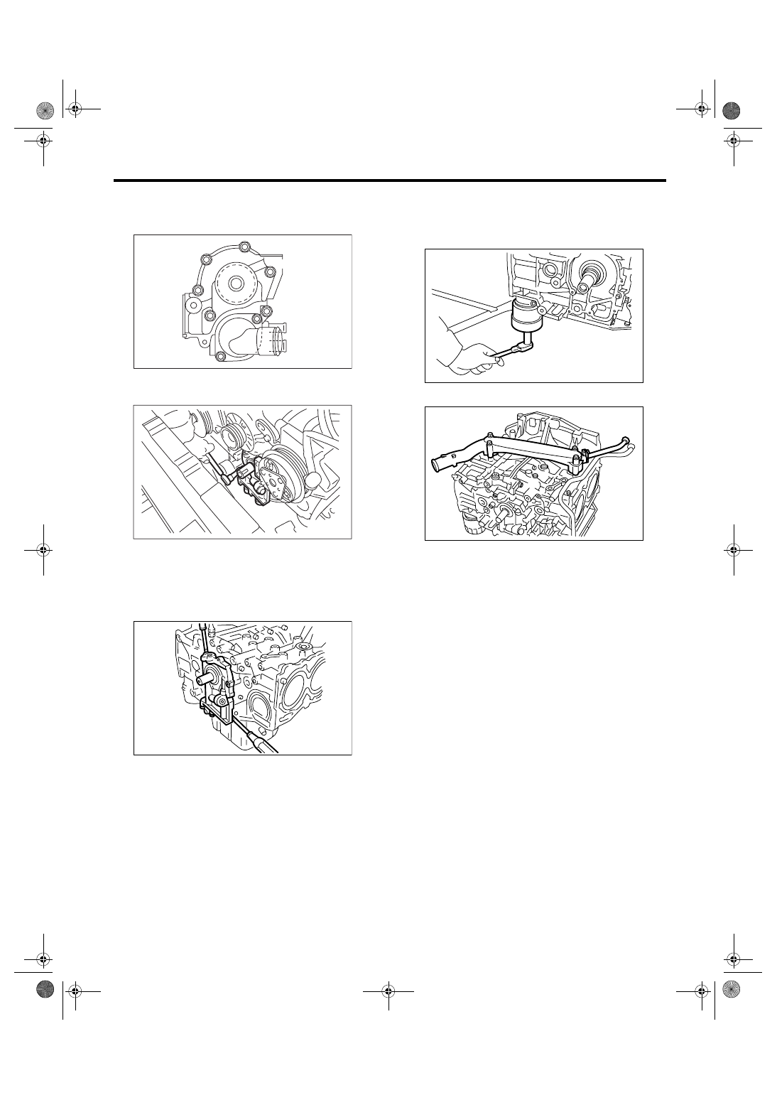
19) Remove the water pump after loosening the
bolts in alphabetical sequence as shown in the fig-
ure.
20) Remove the bolt which installs oil pump to cyl-
inder block.
21) Remove the oil pump from cylinder block using
flat tip screwdriver.
CAUTION:
Be careful not to scratch the mating surface of
cylinder block and oil pump.
22) Removal of oil pan
(1) Place the cylinder block to face the #2 and
#4 piston side upward.
(2) Remove the bolts which secure oil pan to
cylinder block.
(3) Insert an oil pan cutter blade between cylin-
der block-to-oil pan clearance and remove the
oil pan.
NOTE:
Do not use a screwdriver or similar tools in place of
oil pan cutter.
23) Remove the oil strainer stay.
24) Remove the oil strainer.
25) Remove the baffle plate.
26) Remove the oil filter.
27) Remove the water pipe.
ME-02463
(F)
(E)
(D)
(C)
(B)
(A)
LU-00015
ME-00138
ME-00299
ME-00300
ME(H4SO 2.0)-66
MECHANICAL
Cylinder Block
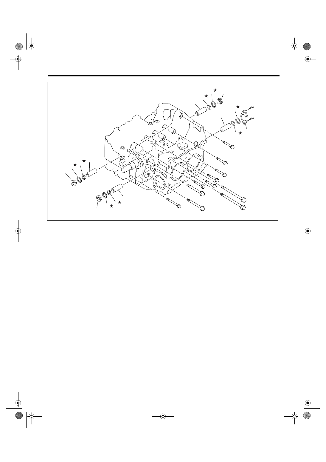
(1)
Service hole plug
(3)
Snap ring
(5)
Service hole cover
(2)
Gasket
(4)
Piston pin
(6)
O-ring
ME-02407
(3)
(4)
(2)
(1)
(3)
(4)
(5)
(6)
(2)
(3)
(2)
(1)
(3)
(4)
(4)
(1)
Нет комментариевНе стесняйтесь поделиться с нами вашим ценным мнением.
Текст