Subaru Legacy (2005 year). Service manual — part 68
ME(H4SO 2.0)-55
MECHANICAL
Camshaft
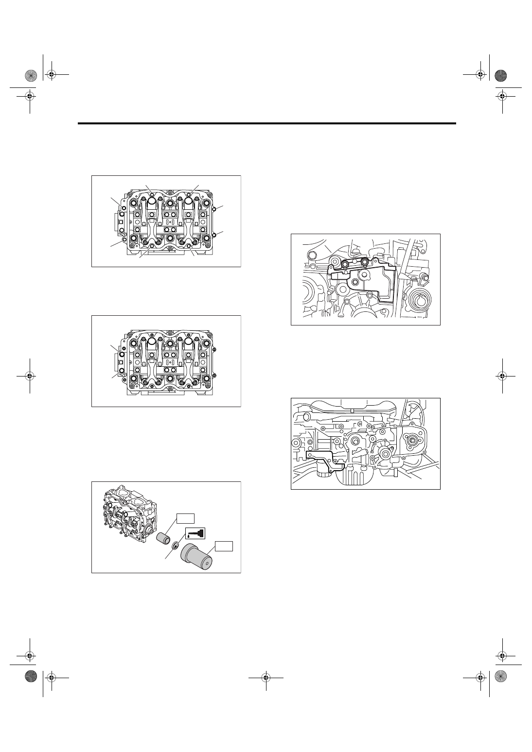
(6) Tighten the bolts (o) through (v) in alphabet-
ical sequence.
Tightening torque:
10 N
⋅
m (1.0 kgf-m, 7.4 ft-lb)
(7) Tighten the bolts (w) and (x) in alphabetical
sequence.
Tightening torque:
10 N
⋅
m (1.0 kgf-m, 7.4 ft-lb)
3) Apply a coat of engine oil to oil seal lips and in-
stall the oil seal (A) on camshaft using ST1 and
ST2.
NOTE:
Use a new oil seal.
ST1
499597000
OIL SEAL GUIDE
ST2
499587500
OIL SEAL INSTALLER
4) Install the plug using ST.
ST
499587700
CAMSHAFT OIL SEAL IN-
STALLER
5) Adjust the valve clearance. <Ref. to ME(H4SO
2.0)-29, ADJUSTMENT, Valve Clearance.>
6) Install the rocker cover and rocker cover gasket,
and then connect the PCV hose.
NOTE:
Use a new rocker cover gasket.
7) Install the oil level gauge guide. (LH side only)
8) Install the camshaft position sensor support. (LH
side only)
9) Install the tensioner bracket.
Tightening torque:
24.5 N
⋅
m (2.5 kgf-m, 18.1 ft-lb)
10) Install the timing belt cover No. 2 (RH).
Tightening torque:
5 N
⋅
m (0.5 kgf-m, 3.7 ft-lb)
11) Install the timing belt cover No. 2 (LH).
Tightening torque:
5 N
⋅
m (0.5 kgf-m, 3.7 ft-lb)
12) Install the crank sprocket.
<Ref. to ME(H4SO 2.0)-50, INSTALLATION,
Crank Sprocket.>
13) Install the cam sprocket. <Ref. to ME(H4SO
2.0)-48, INSTALLATION, Cam Sprocket.>
14) Install the timing belt. <Ref. to ME(H4SO 2.0)-
44, INSTALLATION, Timing Belt.>
15) Install the timing belt cover.
<Ref. to ME(H4SO 2.0)-42, INSTALLATION, Tim-
ing Belt Cover.>
16) Install the crank pulley. <Ref. to ME(H4SO
2.0)-40, INSTALLATION, Crank Pulley.>
17) Install the V-belts. <Ref. to ME(H4SO 2.0)-37,
INSTALLATION, V-belt.>
ME-00270
( o )
( r )
( q )
( v )
( u )
( p )
( s )
( t )
ME-00271
( x )
( w )
ME-02596
(A)
ST2
ST1
ME-00273
ME-00274
ME(H4SO 2.0)-56
MECHANICAL
Camshaft
C: INSPECTION
1. CAMSHAFT
1) Measure the bend, and repair or replace if nec-
essary.
Service limit:
0.020 mm (0.00079 in)
2) Check the journal for damage and wear. Re-
place if faulty.
3) Measure the outer diameter of camshaft journal
and inner diameter of cylinder head journal, and
confirm the difference (oil clearance) between the
two values. If the oil clearance exceeds standard,
replace the camshaft or cylinder head as neces-
sary.
4) Check the cam face condition, and remove the
minor faults by grinding with oil stone. Measure the
cam height H. If it exceeds standard, replace it.
Cam height H:
Cam base circle diameter A:
Intake: 34.00 mm (1.3386 in)
Exhaust: 34.00 mm (1.3386 in)
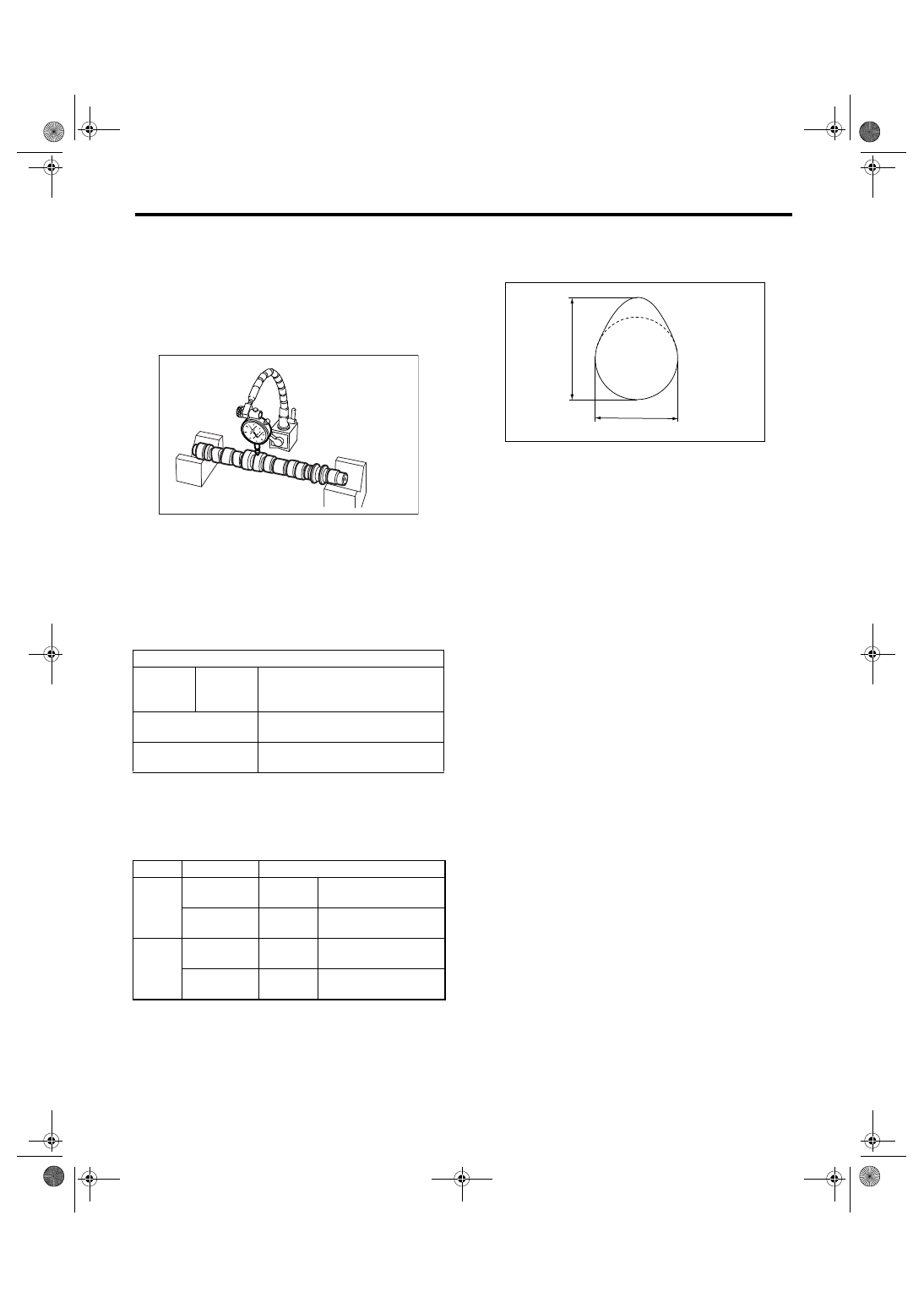
5) Measure the thrust clearance of camshaft with
setting the dial gauge at end of camshaft. If the
thrust clearance exceeds the standard, replace the
camshaft caps and cylinder head as a set. If neces-
sary, replace the camshaft.
Standard:
0.030 — 0.090 mm (0.0012 — 0.0035 in)
Unit: mm (in)
Clear-
ance at
journal
Standard
0.055 — 0.090
(0.0022 — 0.0035)
Camshaft journal O.D.
31.928 — 31.945
(1.2570 — 1.2577)
Journal hole I.D.
32.000 — 32.018
(1.2598 — 1.2605)
Model
Parts
Unit: mm (in)
2.0 L
Intake
Standard
39.646 — 39.746
(1.5609 — 1.5648)
Exhaust
Standard
39.351 — 39.451
(1.5493 — 1.5532)
2.5 L
Intake
Standard
39.485 — 39.585
(1.5545 — 1.5585)
Exhaust
Standard
39.904 — 40.004
(1.5710 — 1.5750)
ME-00275
ME-00276
H
A
ME(H4SO 2.0)-57
MECHANICAL
Cylinder Head
20.Cylinder Head
A: REMOVAL
1) Remove the V-belts. <Ref. to ME(H4SO 2.0)-37,
REMOVAL, V-belt.>
2) Remove the crank pulley. <Ref. to ME(H4SO
2.0)-40, REMOVAL, Crank Pulley.>
3) Remove the timing belt cover. <Ref. to
ME(H4SO 2.0)-42, REMOVAL, Timing Belt Cov-
er.>
4) Remove the timing belt. <Ref. to ME(H4SO 2.0)-
43, REMOVAL, Timing Belt.>
5) Remove the cam sprocket. <Ref. to ME(H4SO
2.0)-48, REMOVAL, Cam Sprocket.>
6) Remove the intake manifold. <Ref. to FU(H4SO
2.0)-11, REMOVAL, Intake Manifold.>
7) Remove the bolt which installs A/C compressor
bracket on cylinder head.
8) Remove the valve rocker assembly. <Ref. to
ME(H4SO 2.0)-51, REMOVAL, Valve Rocker As-
sembly.>
9) Remove the camshaft. <Ref. to ME(H4SO 2.0)-
53, REMOVAL, Camshaft.>
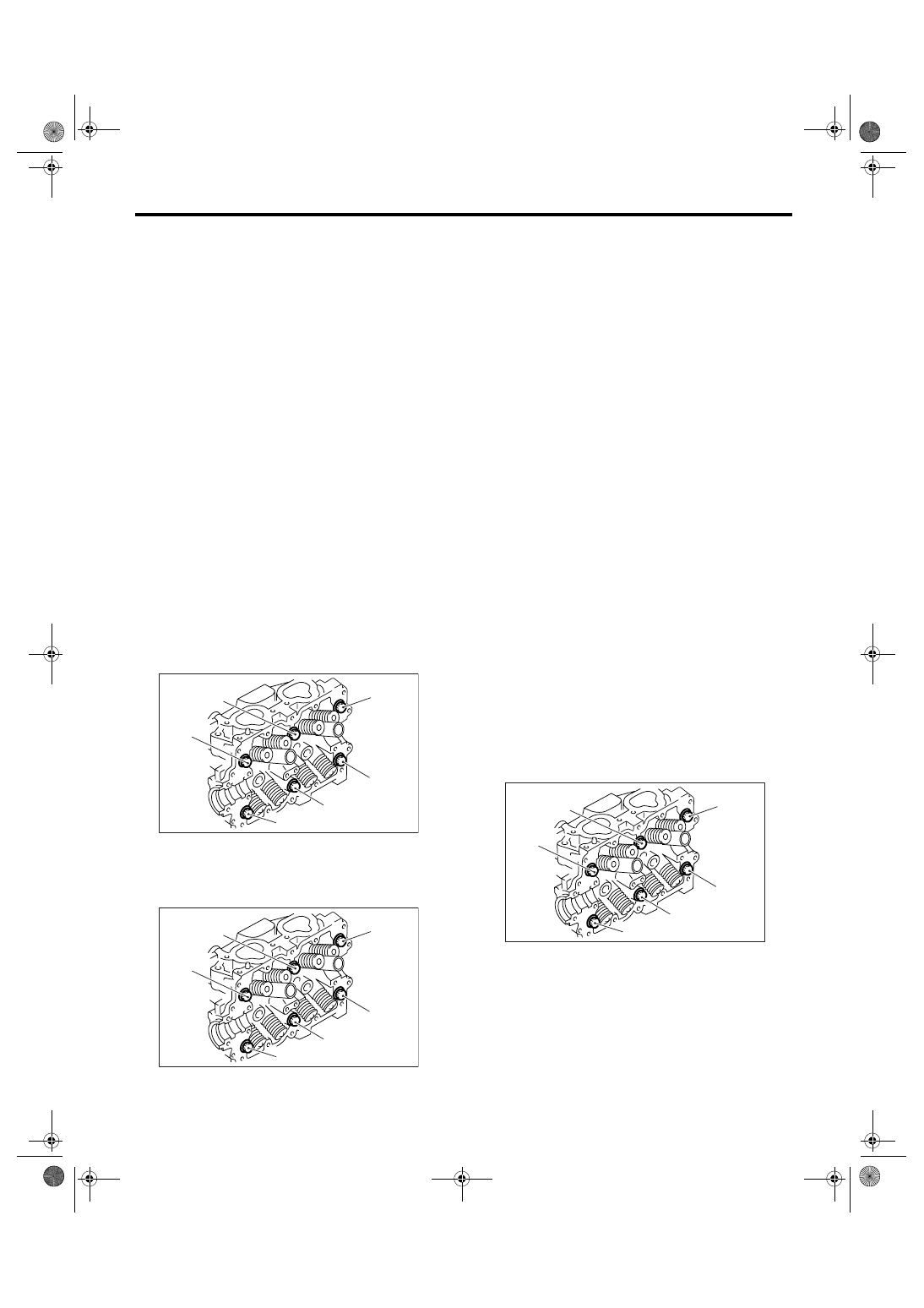
10) Remove the cylinder head bolts in alphabetical
sequence as shown in the figure.
NOTE:
Leave the bolts (a) and (c) engaged by three or four
threads to prevent the cylinder head from falling.
11) While tapping the cylinder head with a plastic
hammer, separate it from cylinder block.
12) Remove the bolts (a) and (c) to remove the cyl-
inder head.
13) Remove the cylinder head gasket.
CAUTION:
Be careful not to scratch the mating surface of
cylinder head and cylinder block.
14) Similarly, remove the cylinder head RH.
B: INSTALLATION
1) Install the cylinder head and gaskets on cylinder
block.
CAUTION:
• Use new cylinder head gaskets.
• Be careful not to scratch the mating surface
of cylinder block and cylinder head.
2) Tighten the cylinder head bolts.
(1) Apply a coat of engine oil to washers and
bolt threads.
(2) Tighten all bolts to 29 N
⋅m (3.0 kgf-m, 22 ft-
lb) in alphabetical sequence. Then tighten all
bolts to 69 N
⋅m (7.0 kgf-m, 51 ft-lb) in alphabet-
ical sequence.
(3) Back off all bolts by 180
° in reverse order of
installation, and back them off again by 180
°.
(4) Tighten all bolts to 42 N
⋅m (4.3 kgf-m, 31 ft-
lb) in alphabetical sequence.
(5) Tighten all bolts by 80 — 90
° in alphabetical
sequence.
(6) Tighten all bolts by 40 — 45
° in alphabetical
sequence.
CAUTION:
Do not tighten the bolts more than 45
°
(7) Further tighten the bolts (A) and (B) by 40 —
45
°.
CAUTION:
Ensure the total re-tightening angle of the step
(6) and (7) does not exceed 90
°.
3) Install the camshaft. <Ref. to ME(H4SO 2.0)-54,
INSTALLATION, Camshaft.>
4) Install the valve rocker assembly. <Ref. to
ME(H4SO 2.0)-51, INSTALLATION, Valve Rocker
Assembly.>
5) Install the A/C compressor bracket on cylinder
head.
6) Install the intake manifold.
<Ref. to FU(H4SO 2.0)-12, INSTALLATION, Intake
Manifold.>
ME-00278
( c )
( b )
( f )
( d )
( a )
( e )
ME-00278
( c )
( b )
( f )
( d )
( a )
( e )
ME-00279
( c )
( b )
( f )
( d )
( a )
( e )
ME(H4SO 2.0)-58
MECHANICAL
Cylinder Head
7) Install the cam sprocket. <Ref. to ME(H4SO
2.0)-48, INSTALLATION, Cam Sprocket.>
8) Install the timing belt. <Ref. to ME(H4SO 2.0)-
44, INSTALLATION, Timing Belt.>
9) Install the timing belt cover.
<Ref. to ME(H4SO 2.0)-42, INSTALLATION, Tim-
ing Belt Cover.>
10) Install the crank pulley. <Ref. to ME(H4SO
2.0)-40, INSTALLATION, Crank Pulley.>
11) Install the V-belts. <Ref. to ME(H4SO 2.0)-37,
INSTALLATION, V-belt.>
C: DISASSEMBLY
1) Place the cylinder head on the ST.
ST
498267800
CYLINDER HEAD TABLE
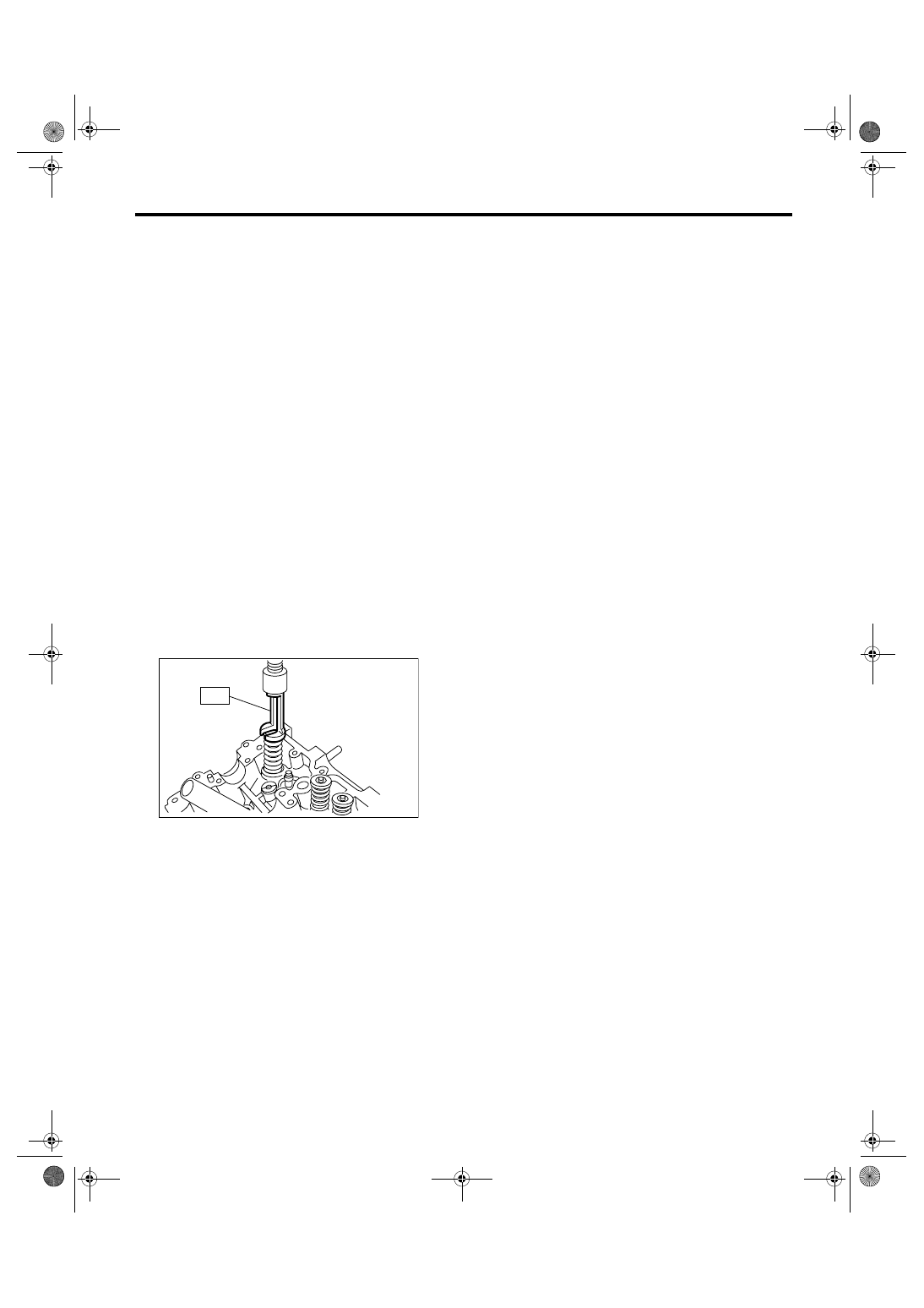
2) Set the ST on valve spring. Compress the valve
spring and remove the valve spring retainer key.
Remove each valve and valve spring.
ST
499718000
VALVE SPRING REMOVER
NOTE:
Keep all the removed parts in order for re-installing
in their original positions.
CAUTION:
• Mark each valve to prevent confusion.
• Use extreme care not to damage the lips of
the intake valve oil seals and exhaust valve oil
seals.
ME-00280
ST
Нет комментариевНе стесняйтесь поделиться с нами вашим ценным мнением.
Текст