Subaru Legacy (2005 year). Service manual — part 542
4AT(diag)-5
AUTOMATIC TRANSMISSION (DIAGNOSTICS)
General Description
3. General Description
A: CAUTION
• Supplemental Restraint System “Airbag”
The airbag system wiring harness is routed near
the TCM.
CAUTION:
• All the airbag system wiring harnesses and
connectors are colored yellow. Do not use an
electric test equipment on these circuits.
• Be careful not to damage the airbag system
wiring harness when performing diagnostics or
servicing the TCM.
• Measurement
When measuring the voltage and resistance of the
ECM, TCM or each sensor, use a tapered pin with
a diameter of less than 0.64 mm (0.025 in) in order
to avoid poor contact. Do not insert a pin of more
than 0.65 mm (0.026 in) diameter.
B: INSPECTION
1. BATTERY
Measure the battery voltage and specific gravity of
electrolyte.
Standard voltage: 12 V or more
Specific gravity: 1.260 or more
2. TRANSMISSION GROUND
Make sure that the ground terminal bolt is tightened
securely.
• Chassis side
Tightening torque:
13 N
⋅
m (1.3 kgf-m, 9.6 ft-lb)
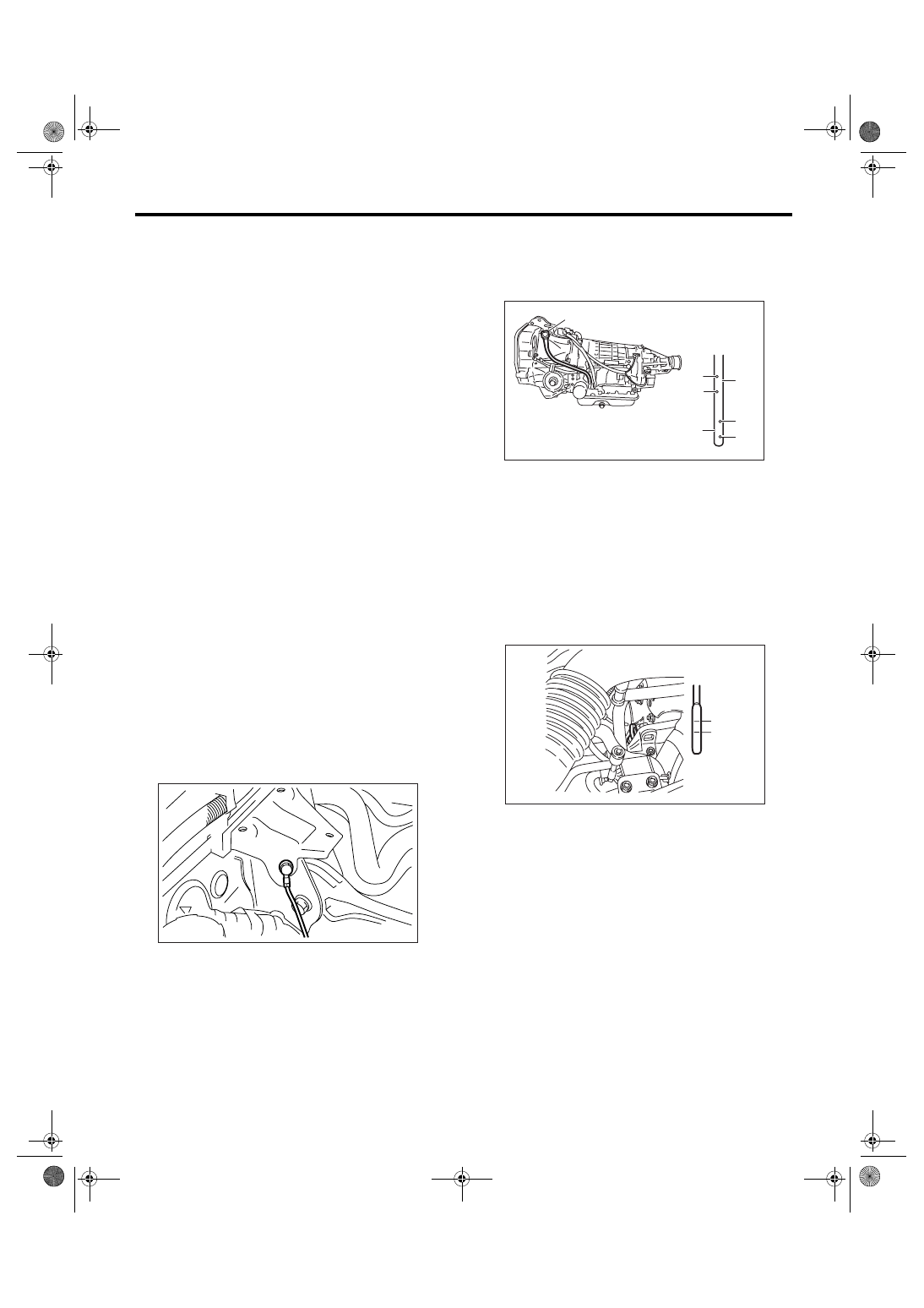
3. ATF LEVEL
Make sure that ATF level is the specified amount.
<Ref. to 4AT-31, INSPECTION, Automatic Trans-
mission Fluid.>
4. FRONT DIFFERENTIAL OIL LEVEL
Make sure the front differential oil level is the spec-
ified amount. <Ref. to 4AT-33, INSPECTION, Dif-
ferential Gear Oil.>
AT-01464
(A) Level gauge
(B) Check position when “HOT”
(C) Upper level
(D) Lower level
(E) Check position when “COLD”
(A) Upper level
(B) Lower level
PI-00105
COLD
LF
HOT
LF
(A)
(C)
(D)
(C)
(D)
(E)
(B)
AT-00317
(A)
(B)
L
F
4AT(diag)-6
AUTOMATIC TRANSMISSION (DIAGNOSTICS)
General Description
5. OPERATION OF SHIFT SELECT LEVER
Make sure there is no noise, dragging or contact
pattern in each select lever range.
WARNING:
Stop the engine while checking operation of the
select lever.
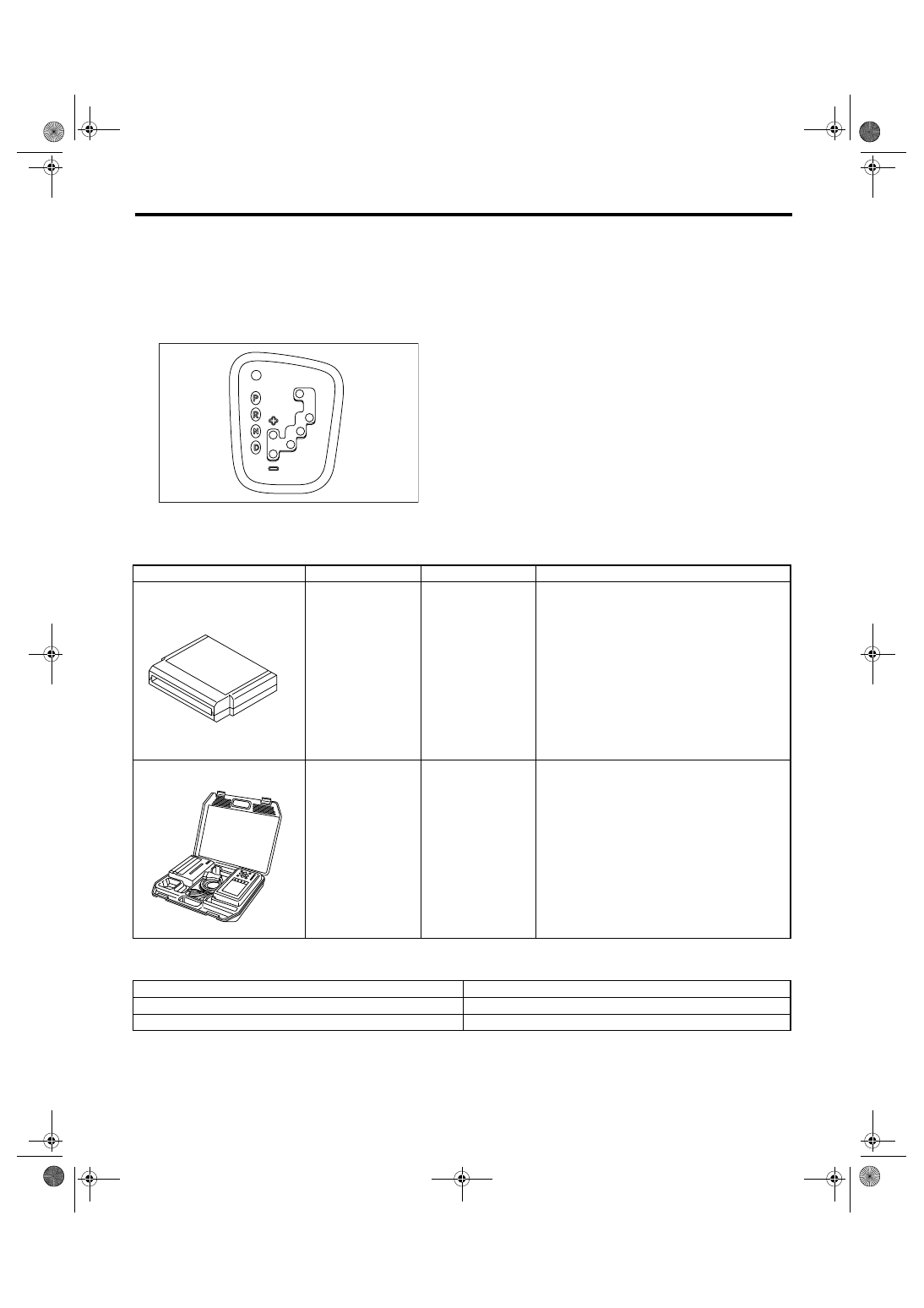
C: PREPARATION TOOL
1. SPECIAL TOOL
2. GENERAL TOOL
AT-02048
ILLUSTRATION
TOOL NUMBER
DESCRIPTION
REMARKS
18482AA000
(Newly adopted tool)
CARTRIDGE
Troubleshooting for electrical system.
22771AA030
SUBARU SELECT
MONITOR KIT
Troubleshooting for electrical system.
• English: 22771AA030 (Without printer)
• German: 22771AA070 (Without printer)
• French: 22771AA080 (Without printer)
• Spanish: 22771AA090 (Without printer)
TOOL NAME
REMARKS
Circuit tester
Used for measuring resistance, voltage and current.
Oscilloscope
Used for measuring sensor.
ST18482AA000
ST22771AA030
4AT(diag)-7
AUTOMATIC TRANSMISSION (DIAGNOSTICS)
Electrical Component Location
4. Electrical Component Location
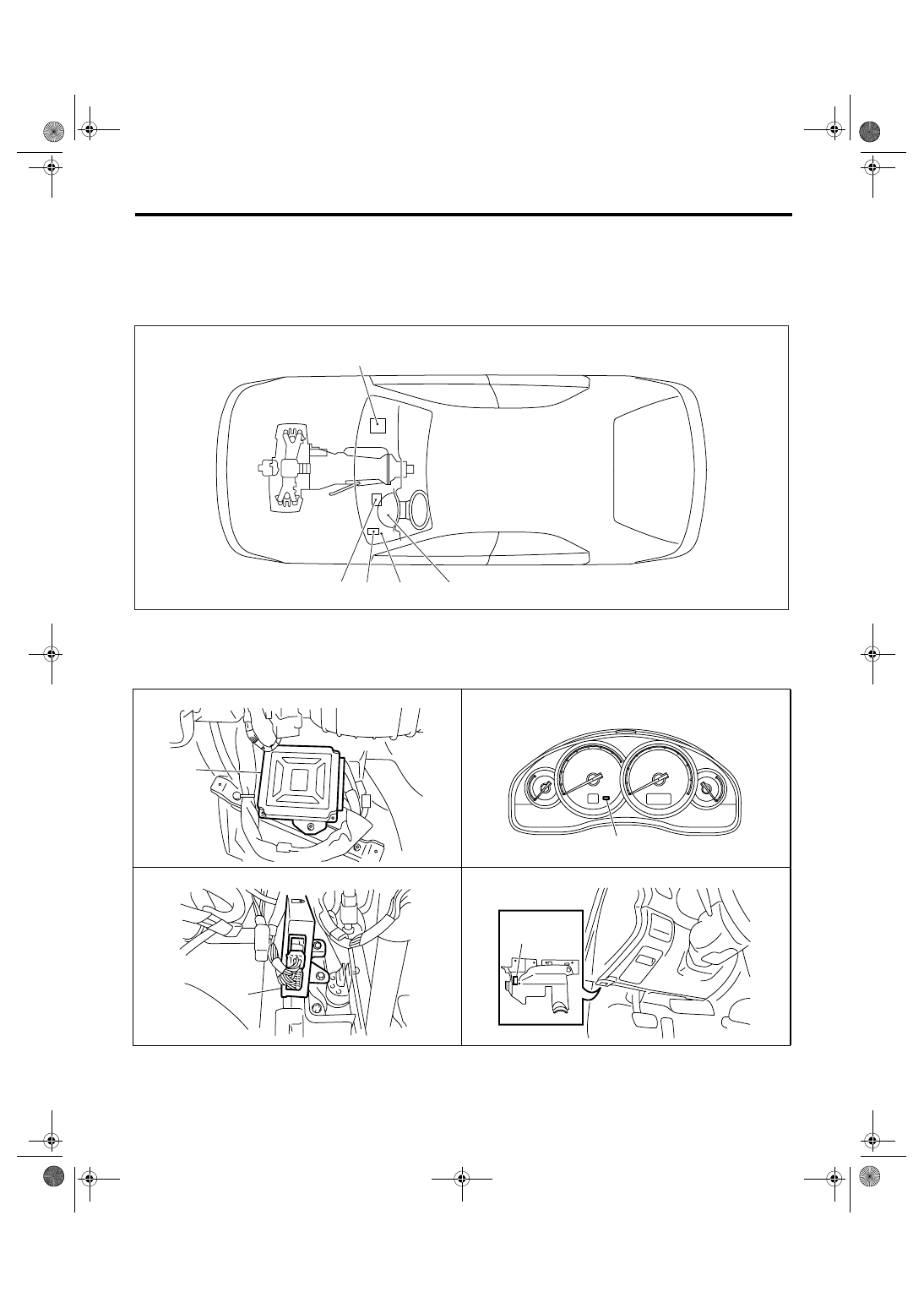
A: LOCATION
1. CONTROL MODULE
• LHD model
(1)
Engine control module (ECM)
(3)
Transmission control module
(TCM)
(4)
Data link connector
(2)
SPORT indicator light (AT warning
light)
(5)
Body integrated module
(3)
(5)
(2)
(1)
AT-01873
(4)
(1)
AT-01874
AT-01470
(2)
AT-01875
(3)
AT-01877
(4)
4AT(diag)-8
AUTOMATIC TRANSMISSION (DIAGNOSTICS)
Electrical Component Location
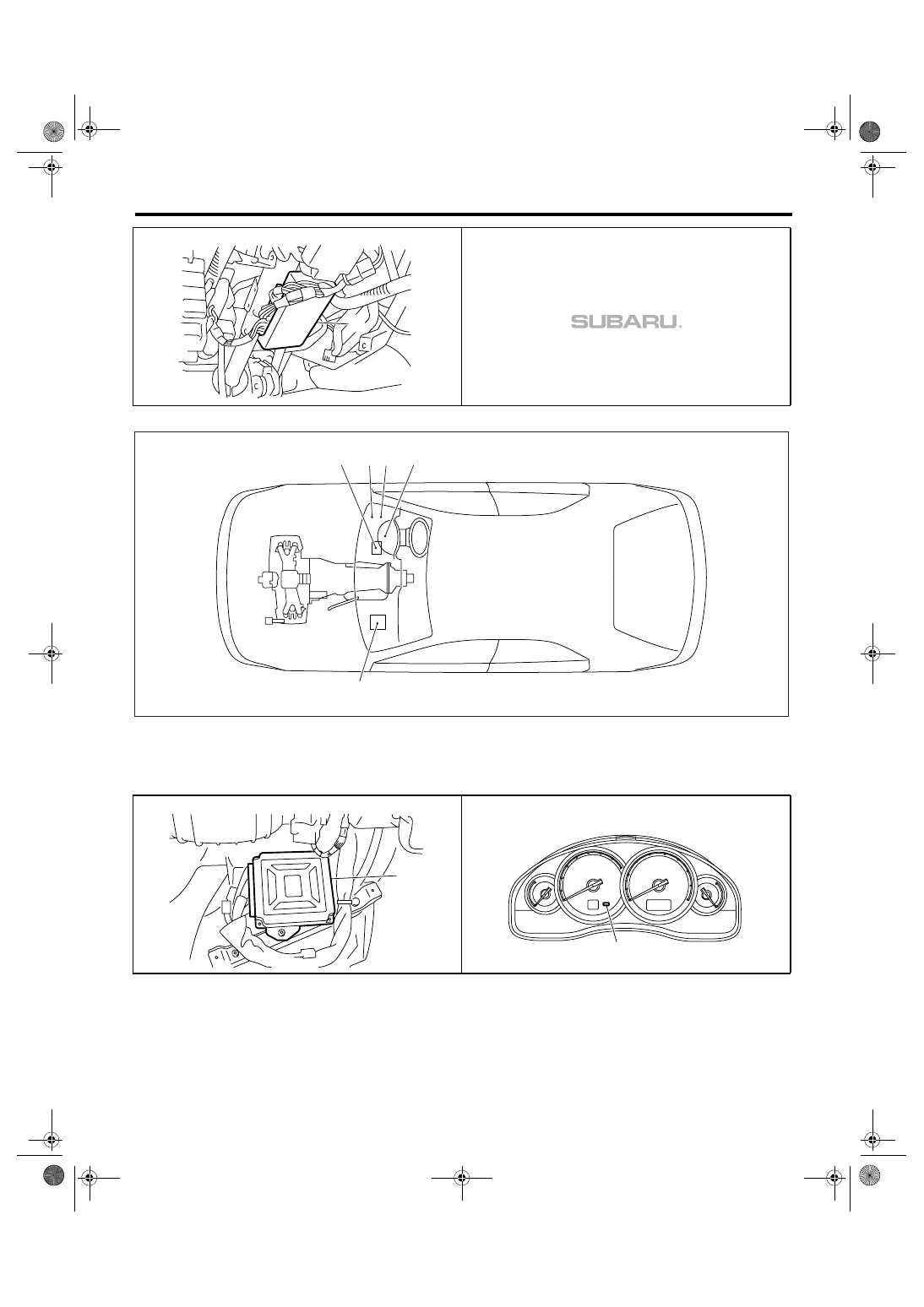
• RHD model
(1)
Engine control module (ECM)
(3)
Transmission control module
(TCM)
(4)
Data link connector
(2)
SPORT indicator light (AT warning
light)
(5)
Body integrated module
AT-01876
(5)
(2)
(3)
(5)
(1)
AT-01467
(4)
(1)
AT-01468
AT-01470
(2)
Нет комментариевНе стесняйтесь поделиться с нами вашим ценным мнением.
Текст