Subaru Legacy (2005 year). Service manual — part 433
EN(H6DO)(diag)-45
ENGINE (DIAGNOSTICS)
Malfunction Indicator Light
B: ACTIVATION OF MALFUNCTION
INDICATOR LIGHT
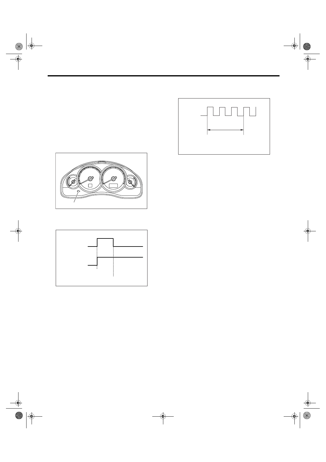
1) When the ignition switch is turned to ON (engine
OFF), the malfunction indicator light (A) in the com-
bination meter illuminates.
NOTE:
If the malfunction indicator light does not illuminate,
perform the diagnosis of malfunction indicator light
circuit or the combination meter circuit. <Ref. to
EN(H6DO)(diag)-46, MALFUNCTION INDICATOR
LIGHT DOES NOT COME ON, Malfunction Indica-
tor Light.>
2) After starting the engine, the malfunction indica-
tor light goes out. If it does not, either the engine or
emission control system is malfunctioning.
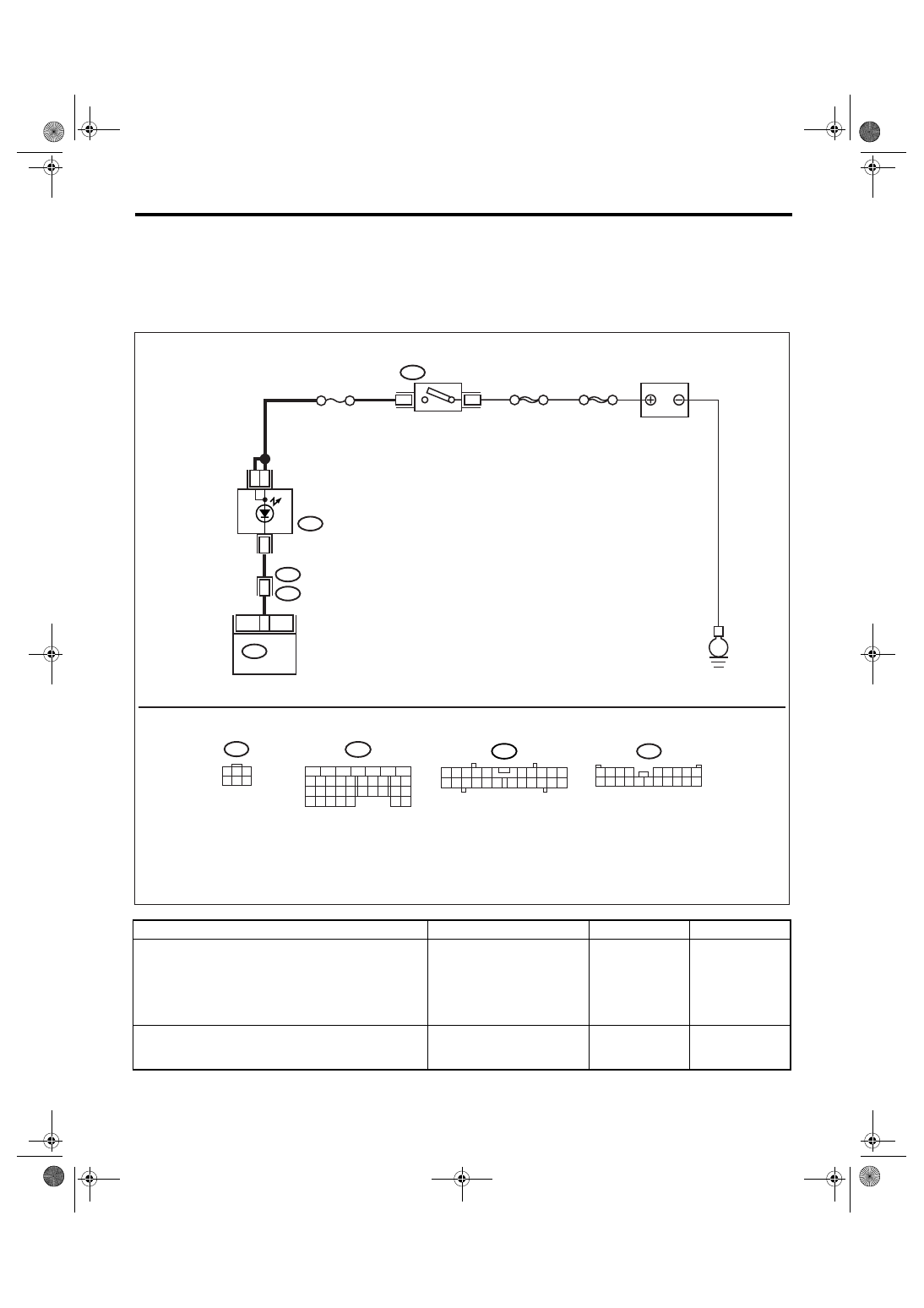
3) Turn the ignition switch to OFF and connect the
test mode connector.
(1) When the ignition switch is turned to ON
(engine OFF), the malfunction indicator light illu-
minates.
(2) After the engine starts, malfunction indicator
light blinks in a cycle of 0.5 Hz. (during diagno-
sis)
(3) Malfunction indicator light blinks at a cycle of
3 Hz after diagnosis if there is no trouble. Mal-
function indicator light illuminates if faulty.
(1) No faulty
(2) Trouble occurs
(3) ON
(4) OFF
(5) Ignition switch ON
(6) Engine start
EN-01984
(A)
EN-01679
(1)
(2)
(5)
(6)
(3)
(4)
(3)
(4)
(1) ON
(2) OFF
(3) Ignition switch ON
(4) 1 second
EN-01681
(2)
(1)
(4)
(3)
EN(H6DO)(diag)-46
ENGINE (DIAGNOSTICS)
Malfunction Indicator Light
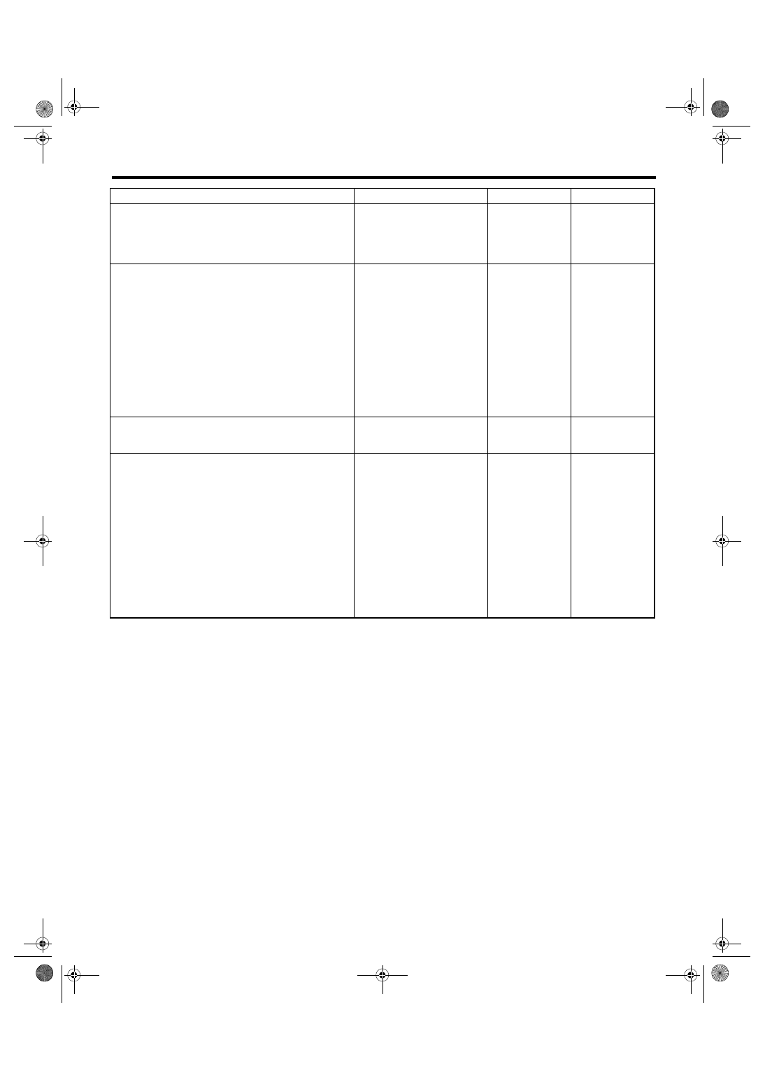
C: MALFUNCTION INDICATOR LIGHT DOES NOT COME ON
DIAGNOSIS:
The malfunction indicator light circuit is open or shorted.
TROUBLE SYMPTOM:
When the ignition switch is turned to ON (engine OFF), malfunction indicator light does not come on.
WIRING DIAGRAM:
Step
Check
Yes
No
1
CHECK OUTPUT SIGNAL FROM ECM.
1) Turn the ignition switch to ON.
2) Measure the voltage between ECM con-
nector and chassis ground.
Connector & terminal
(B134) No. 17 (+) — Chassis ground (
−
):
Is the voltage less than 1 V?
2
CHECK POOR CONTACT.
Check for poor connection by shaking or pull-
ing ECM connector and harness.
Does the malfunction indicator
light illuminate?
Repair the poor
contact in ECM
connector.
EN-03487
BATTERY
3
B72
i3
B38
B134
IGNITION
SWITCH
COMBINATION
METER
i10
SBF-6
6
17
ECM
4
B72
8
MAIN SBF
No.5
16
E
3
1
3
4 5 6
2
B134
5
6
7
8
2
1
9
4
3
10
24
22 23
25
11 12 13 14 15
26 27
28
16 17
18 19 20 21
33 34
29
32
30 31
B38
1 2 3 4
5 6 7 8 9
10 11 12 13 14 15 16 17 18 19 20
i10
2
1
3 4
6 7 8 9 10
22
21
20
19
18
17
16
15
14
13
12
11
5
EN(H6DO)(diag)-47
ENGINE (DIAGNOSTICS)
Malfunction Indicator Light
3
CHECK ECM CONNECTOR.
Check the connection of ECM connector.
Is the ECM connector correctly
connected?
Replace the ECM.
<Ref. to
FU(H6DO)-34,
Engine Control
Module (ECM).>
Repair the con-
nection of ECM
connector.
4
CHECK HARNESS BETWEEN COMBINA-
TION METER AND ECM CONNECTOR.
1) Turn the ignition switch to OFF.
2) Remove the combination meter. <Ref. to
IDI-15, Combination Meter.>
3) Disconnect the connector from ECM and
combination meter.
4) Measure the resistance of harness
between ECM and combination meter connec-
tor.
Connector & terminal
(B134) No. 17 — (i10) No. 16:
Is the resistance less than 1
Ω?
Repair the har-
ness and connec-
tor.
NOTE:
In this case, repair
the following:
• Open circuit of
harness between
ECM and combi-
nation meter con-
nector
• Poor contact in
coupling connector
5
CHECK POOR CONTACT.
Check poor contact in combination meter con-
nector.
Is there poor contact in combi-
nation meter connector?
Repair poor con-
tact in combination
meter connector.
6
CHECK HARNESS BETWEEN COMBINA-
TION METER AND IGNITION SWITCH CON-
NECTOR.
1) Turn the ignition switch to ON.
2) Measure the voltage between combination
meter connector and chassis ground.
Connector & terminal
(i10) No. 3 (+) — Chassis ground (
−
):
(i10) No. 4 (+) — Chassis ground (
−
):
Is the voltage more than 10 V? Replace the meter
case assembly of
combination
meter. <Ref. to IDI-
15, Combination
Meter.>
Check the follow-
ing and repair if
necessary.
NOTE:
• Blown out fuse
(No. 5)
• Open or short
circuit of harness
between fuse (No.
5) and battery ter-
minal
• Poor contact in
ignition switch con-
nector
Step
Check
Yes
No
EN(H6DO)(diag)-48
ENGINE (DIAGNOSTICS)
Malfunction Indicator Light
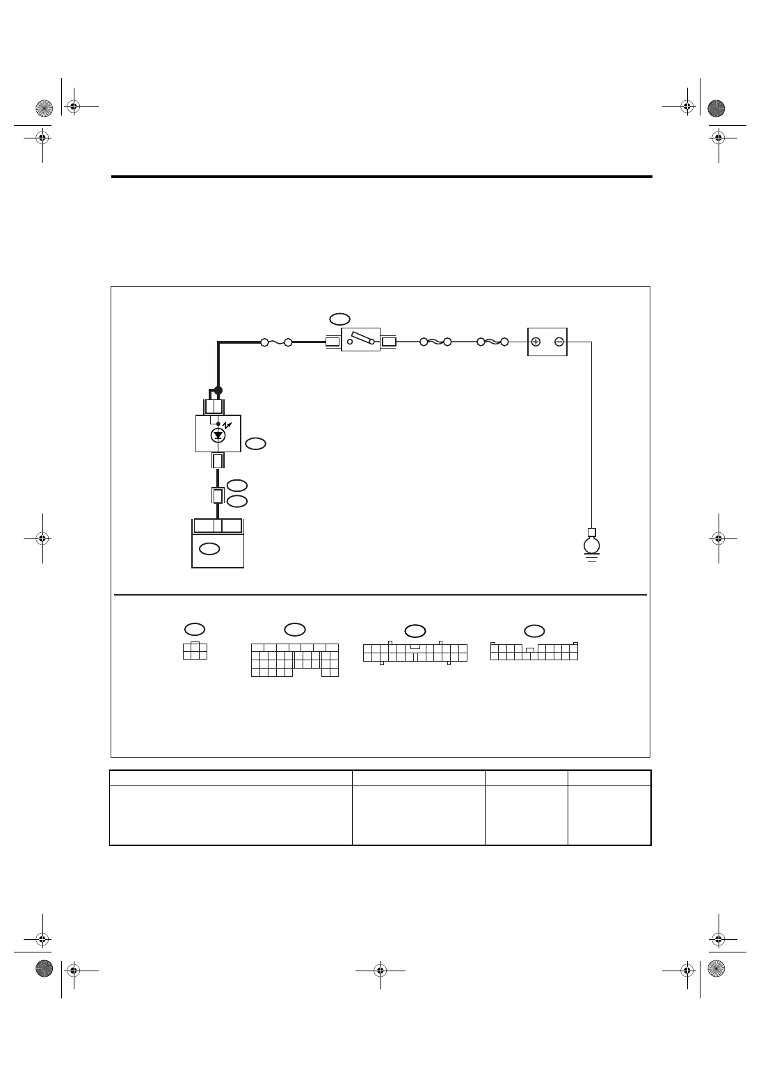
D: MALFUNCTION INDICATOR LIGHT DOES NOT GO OFF.
DIAGNOSIS:
The malfunction indicator light circuit is shorted.
TROUBLE SYMPTOM:
Although malfunction indicator light comes on when the engine runs, DTC is not shown on the Subaru Select
Monitor display.
WIRING DIAGRAM:
Step
Check
Yes
No
1
CHECK HARNESS BETWEEN COMBINA-
TION METER AND ECM CONNECTOR.
1) Turn the ignition switch to OFF.
2) Disconnect the connector from ECM.
3) Turn the ignition switch to ON.
Does the malfunction indicator
light illuminate?
Repair short circuit
of harness
between combina-
tion meter and
ECM connector.
Replace the ECM.
<Ref. to
FU(H6DO)-34,
Engine Control
Module (ECM).>
EN-03487
BATTERY
3
B72
i3
B38
B134
IGNITION
SWITCH
COMBINATION
METER
i10
SBF-6
6
17
ECM
4
B72
8
MAIN SBF
No.5
16
E
3
1
3
4 5 6
2
B134
5
6
7
8
2
1
9
4
3
10
24
22 23
25
11 12 13 14 15
26 27
28
16 17
18 19 20 21
33 34
29
32
30 31
B38
1 2 3 4
5 6 7 8 9
10 11 12 13 14 15 16 17 18 19 20
i10
2
1
3 4
6 7 8 9 10
22
21
20
19
18
17
16
15
14
13
12
11
5
Нет комментариевНе стесняйтесь поделиться с нами вашим ценным мнением.
Текст