Subaru Legacy (2005 year). Service manual — part 259
EC(H4DOTC)-3
EMISSION CONTROL (AUX. EMISSION CONTROL DEVICES)
Front Catalytic Converter
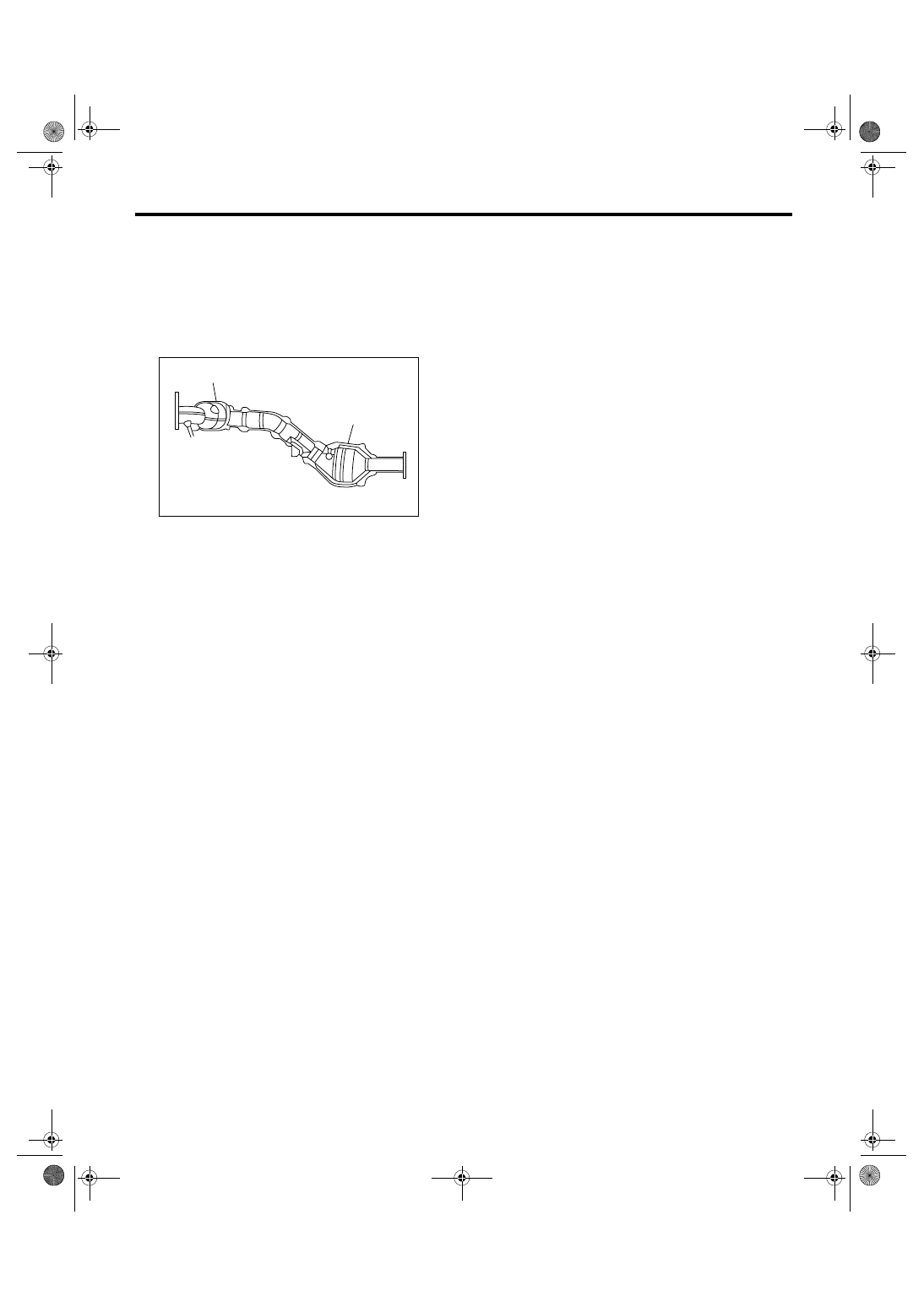
2. Front Catalytic Converter
A: REMOVAL
1) Remove the center exhaust pipe.
<Ref. to EX(H4DOTC)-6, REMOVAL, Center Ex-
haust Pipe.>
2) Separate the front catalytic converter (A) from
rear catalytic converter (B).
B: INSTALLATION
Install in the reverse order of removal.
NOTE:
Always use new gasket.
C: INSPECTION
1) Make sure there are no exhaust leaks from con-
nections and welds.
2) Make sure there are no holes or rusting.
(A)
(B)
EC-00217

EC(H4DOTC)-4
Vehicle-id:
SIE-id:S140036a18:A:REMOVAL
∼
EMISSION CONTROL (AUX. EMISSION CONTROL DEVICES)
Rear Catalytic Converter
3. Rear Catalytic Converter
A: REMOVAL
1) Remove the center exhaust pipe.
<Ref. to EX(H4DOTC)-6, REMOVAL, Center Ex-
haust Pipe.>
2) Separate the rear catalytic converter (B) from
front catalytic converter (A).
B: INSTALLATION
Install in the reverse order of removal.
NOTE:
Always use new gasket.
C: INSPECTION
1) Make sure there are no exhaust leaks from con-
nections and welds.
2) Make sure there are no holes or rusting.
(A)
(B)
EC-00217
EC(H4DOTC)-5
EMISSION CONTROL (AUX. EMISSION CONTROL DEVICES)
Canister
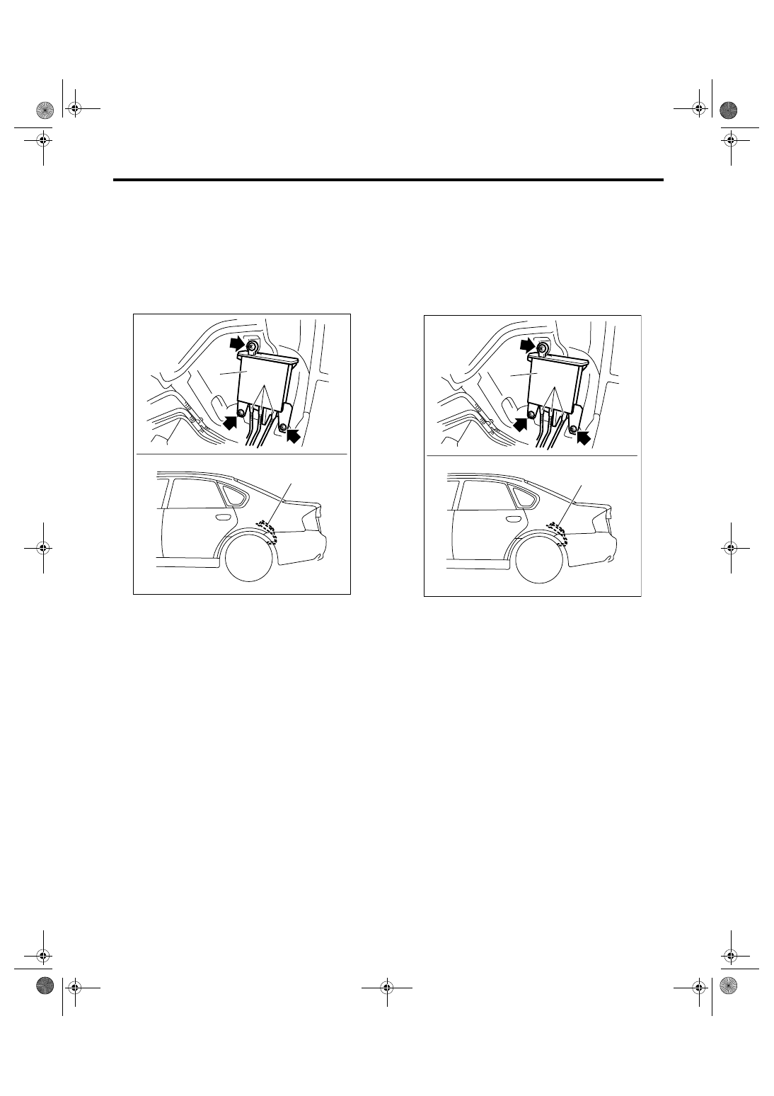
4. Canister
A: REMOVAL
1) Lift-up the vehicle.
2) Remove the rear wheel LH.
3) Remove the rear mud guard LH.
4) Remove the canister protector.
5) Disconnect the quick connector (A).
6) Remove the canister (B) from body.
B: INSTALLATION
Install in the reverse order of removal.
NOTE:
Make sure there are no damage or dust on the con-
nection of quick connector. If necessary, clean the
seal surface of pipe.
Tightening torque:
8.3 N
⋅
m (0.85 kgf-m, 6.1 ft-lb)
C: INSPECTION
Make sure the canister and canister hoses are not
cracked or loose.
EC-02027
(B)
(B)
(A)
EC-02027
(B)
(B)
(A)
EC(H4DOTC)-6
Vehicle-id:
SIE-id:S140035a18:A:REMOVAL
∼
EMISSION CONTROL (AUX. EMISSION CONTROL DEVICES)
Purge Control Solenoid Valve
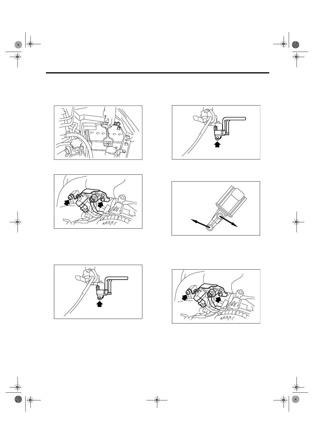
5. Purge Control Solenoid Valve
A: REMOVAL
1) Remove the collector cover.
2) Disconnect the ground cable from battery.
3) Remove the solenoid valve bracket assembly
from intake manifold.
4) Disconnect the connector from purge control so-
lenoid valve.
5) Disconnect the evaporation hose from the intake
manifold and fuel pipe assembly.
6) Remove the purge control solenoid valve from
solenoid valve bracket assembly.
B: INSTALLATION
Install in the reverse order of removal.
Tightening torque:
19 N
⋅
m (1.94 kgf-m, 13.7 ft-lb)
NOTE:
Connect the evaporation hose as shown in the fig-
ure.
Tightening torque:
19 N
⋅
m (1.94 kgf-m, 13.7 ft-lb)
C: INSPECTION
Make sure the hoses are not cracked or loose.
IN-00203
EC-00219
EC-00220
(A) To intake manifold
(B) To fuel pipe ASSY
EC-00220
(A)
(B)
EC-00273
EC-00219
Нет комментариевНе стесняйтесь поделиться с нами вашим ценным мнением.
Текст