Subaru Legacy (2005 year). Service manual — part 246
FU(H4DOTC)-9
FUEL INJECTION (FUEL SYSTEMS)
General Description
(1)
Clip
(14)
Two-way valve hose A
(27)
Filler cap
(2)
Fuel return hose A
(15)
Purge hose A
(28)
Tether
(3)
Evaporation hose
(16)
Purge hose B
(29)
Clip
(4)
Fuel delivery hose A
(17)
Two-way valve hose B
(30)
Fuel hose
(5)
Fuel delivery hose B
(18)
Canister drain hose B
(31)
Purge hose C
(6)
Fuel bypass valve
(19)
Two-way valve drain hose
(32)
Fuel hose connector
(7)
Fuel bypass valve bracket
(20)
Two-way valve
(33)
Purge pipe
(8)
Fuel return hose B
(21)
Two-way valve hose C
(34)
Two-way valve bracket
(9)
Fuel pipe ASSY
(22)
Connector
(10)
Clamp
(23)
Evaporation hose holder
Tightening torque: N
⋅
m (kgf-m, ft-lb)
(11)
Canister
(24)
Fuel filler pipe ASSY
T1: 4.4 (0.45, 3.2)
(12)
Canister protector (Sedan model)
(25)
Filler pipe packing
T2: 7.5 (0.76, 5.5)
(13)
Canister drain hose A
(26)
Filler ring
T3: 8.3 (0.85, 6.1)
FU(H4DOTC)-10
FUEL INJECTION (FUEL SYSTEMS)
General Description
C: CAUTION
• Wear work clothing, including a cap, protective
goggles and protective shoes during operation.
• Remove contamination including dirt and corro-
sion before removal, installation or disassembly.
• Keep the disassembled parts in order and pro-
tect them from dust and dirt.
• Before removal, installation or disassembly, be
sure to clarify the failure. Avoid unnecessary re-
moval, installation, disassembly and replacement.
• Be careful not to burn yourself, because each
part on the vehicle is hot after running.
• Be sure to tighten fasteners including bolts and
nuts to the specified torque.
• Place shop jacks or rigid racks at the specified
points.
• Before disconnecting connectors of sensors or
units, be sure to disconnect the ground cable from
battery.
• Place “NO FIRE” signs near the working area.
• Be careful not to spill fuel on the floor.
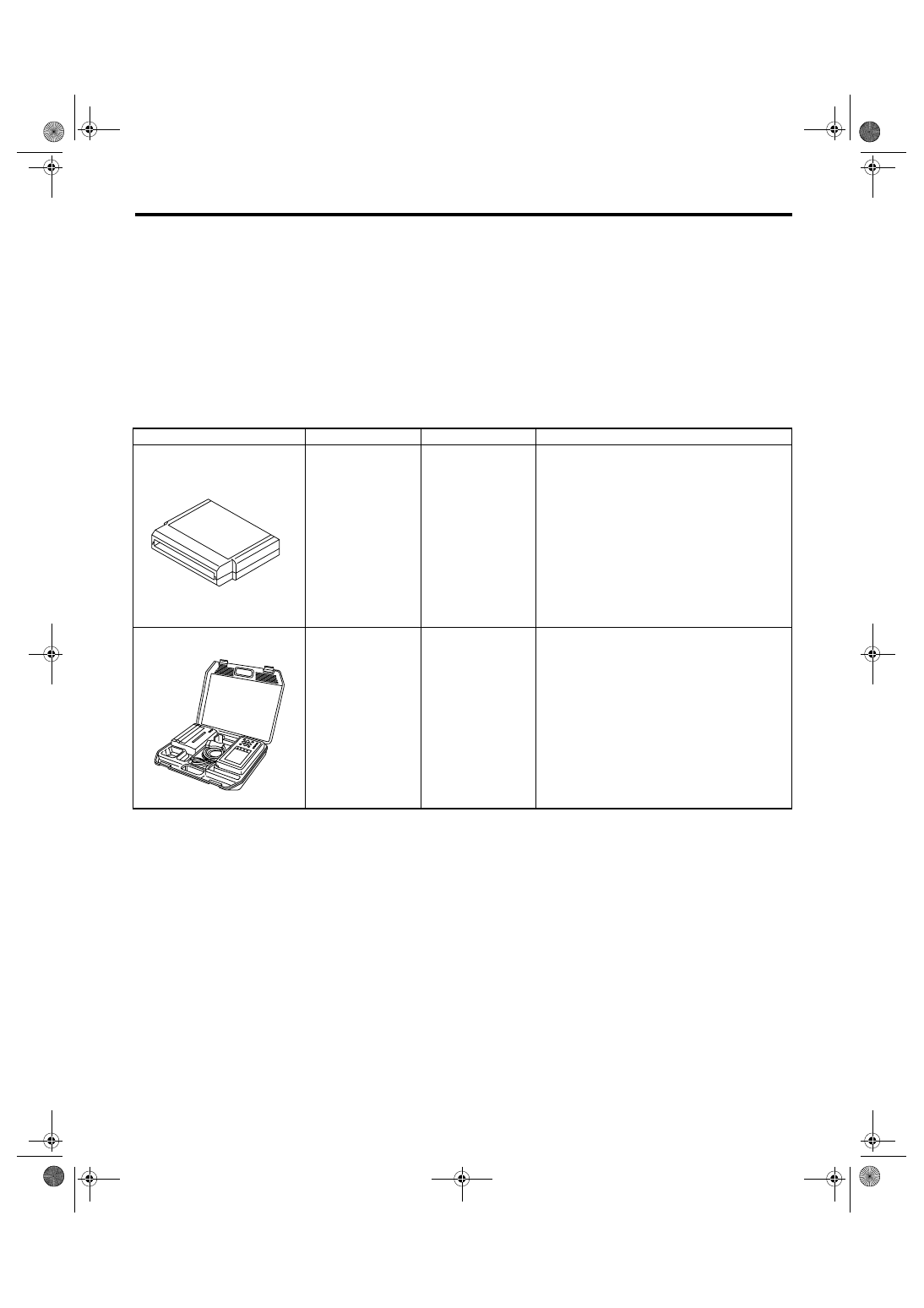
D: PREPARATION TOOL
ILLUSTRATION
TOOL NUMBER
DESCRIPTION
REMARKS
18482AA000
(Newly adopted tool)
CARTRIDGE
Troubleshooting for electrical system.
22771AA030
SUBARU SELECT
MONITOR KIT
Troubleshooting for electrical system.
• English: 22771AA030 (Without printer)
• German: 22771AA070 (Without printer)
• French: 22771AA080 (Without printer)
• Spanish: 22771AA090 (Without printer)
ST18482AA000
ST22771AA030
FU(H4DOTC)-11
FUEL INJECTION (FUEL SYSTEMS)
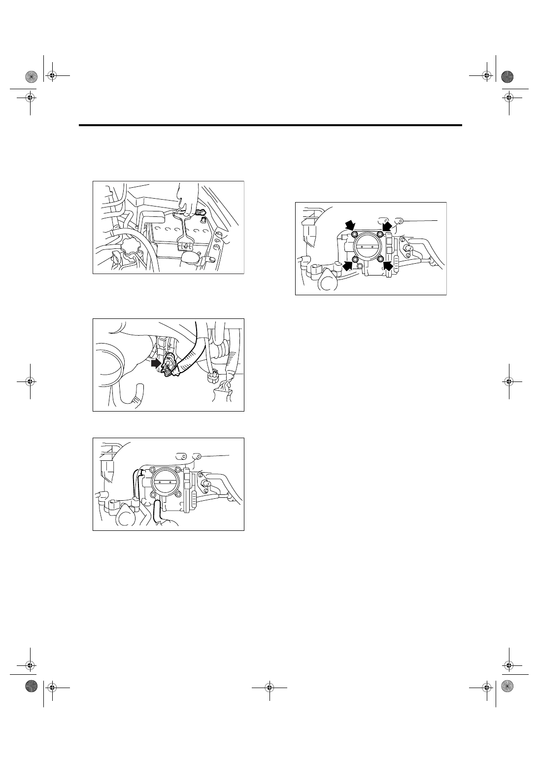
Throttle Body
2. Throttle Body
A: REMOVAL
1) Remove the collector cover.
2) Disconnect the ground cable from battery.
3) Remove the intercooler. <Ref. to IN(H4DOTC)-
12, REMOVAL, Intercooler.>
4) Disconnect the connector from throttle position
sensor.
5) Disconnect the engine coolant hoses from throt-
tle body.
6) Remove the bolts which install throttle body to
the intake manifold.
B: INSTALLATION
Install in the reverse order of removal.
NOTE:
Always use new O-rings.
Tightening torque:
8 N
⋅
m (0.8 kgf-m, 5.9 ft-lb)
IN-00203
FU-01157
FU-01158
FU-01159
FU(H4DOTC)-12
FUEL INJECTION (FUEL SYSTEMS)
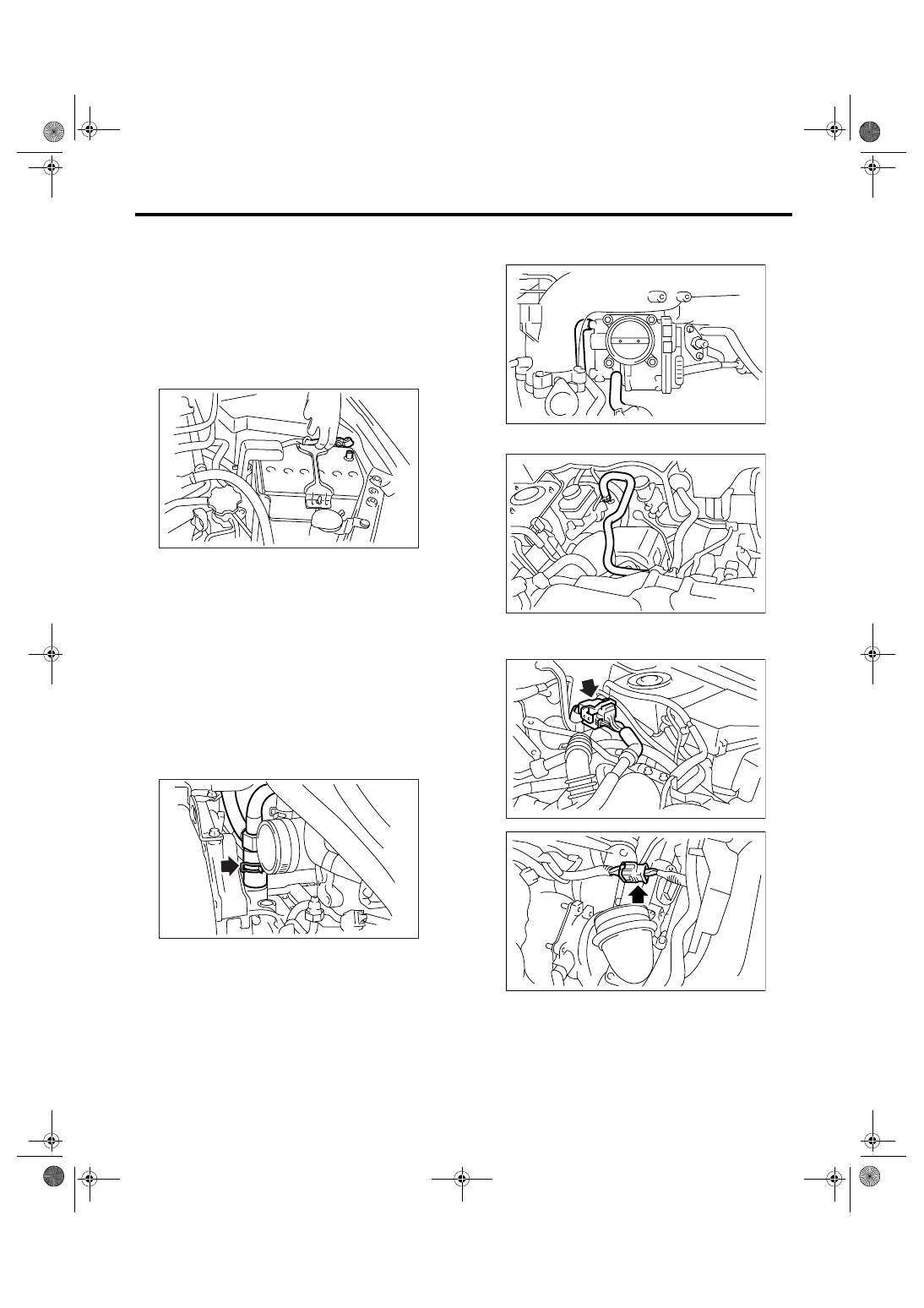
Intake Manifold
3. Intake Manifold
A: REMOVAL
1) Release the fuel pressure.
<Ref. to FU(H4DOTC)-39, RELEASING OF FUEL
PRESSURE, PROCEDURE, Fuel.>
2) Open the fuel filler flap lid, and remove the fuel
filler cap.
3) Remove the collector cover.
4) Disconnect the ground cable from battery.
5) Lift-up the vehicle.
6) Remove the under cover.
7) Drain coolant about 3.0
2 (3.2 US qt, 2.6 Imp
qt).
8) Remove the intake duct from air cleaner case.
9) Remove the intercooler. <Ref. to IN(H4DOTC)-
12, REMOVAL, Intercooler.>
10) Remove the generator. <Ref. to SC(H4SO
2.0)-14, REMOVAL, Generator.>
11) Remove the coolant filler tank. <Ref. to
CO(H4DOTC)-31, REMOVAL, Coolant Filler
Tank.>
12) Disconnect the PCV hose assembly from cylin-
der block.
13) Disconnect the engine coolant hose from throt-
tle body.
14) Disconnect the brake booster hose.
15) Disconnect the engine harness connectors
from bulkhead harness connectors.
IN-00203
FU-01160
FU-01158
FU-01161
FU-01162
FU-01163
Нет комментариевНе стесняйтесь поделиться с нами вашим ценным мнением.
Текст