Subaru Legacy (2005 year). Service manual — part 247
FU(H4DOTC)-13
FUEL INJECTION (FUEL SYSTEMS)
Intake Manifold
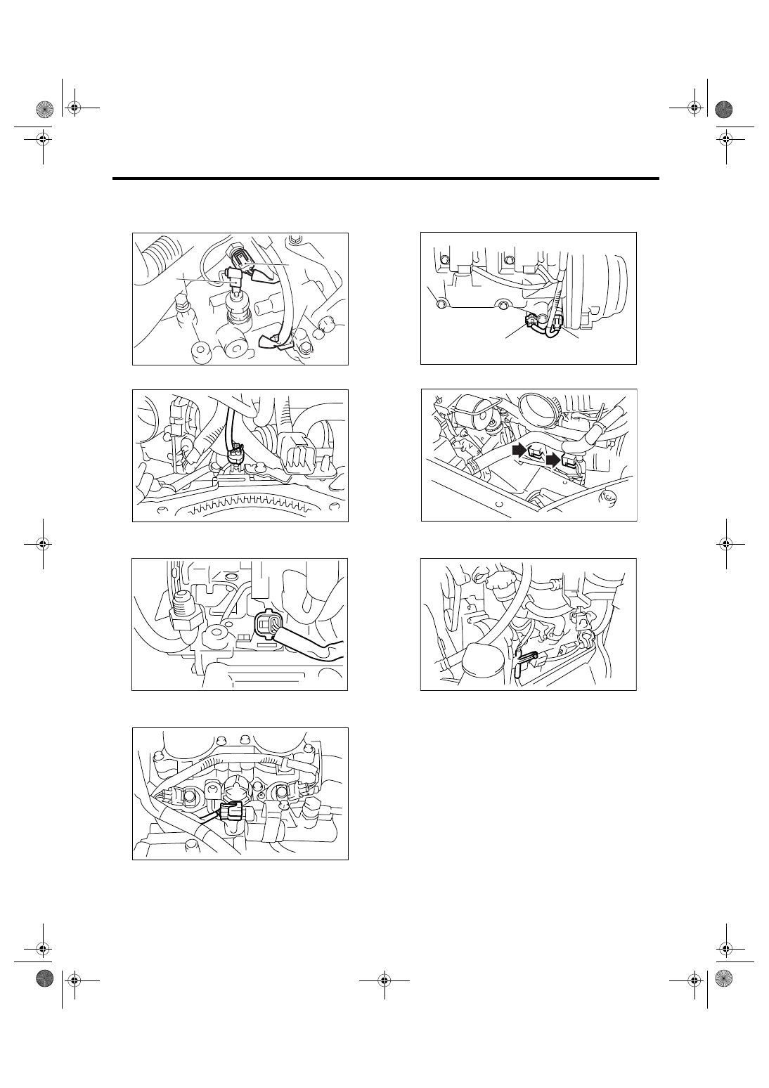
16) Disconnect the connectors from the engine
coolant temperature sensor (A), oil pressure switch
(B) and crankshaft position sensor (C).
17) Disconnect the knock sensor connector.
18) Disconnect the connector from intake camshaft
position sensor.
19) Disconnect the connector from intake oil flow
control solenoid valve.
20) Disconnect the connector from the exhaust
camshaft position sensor (A) and exhaust oil flow
control solenoid valve (B).
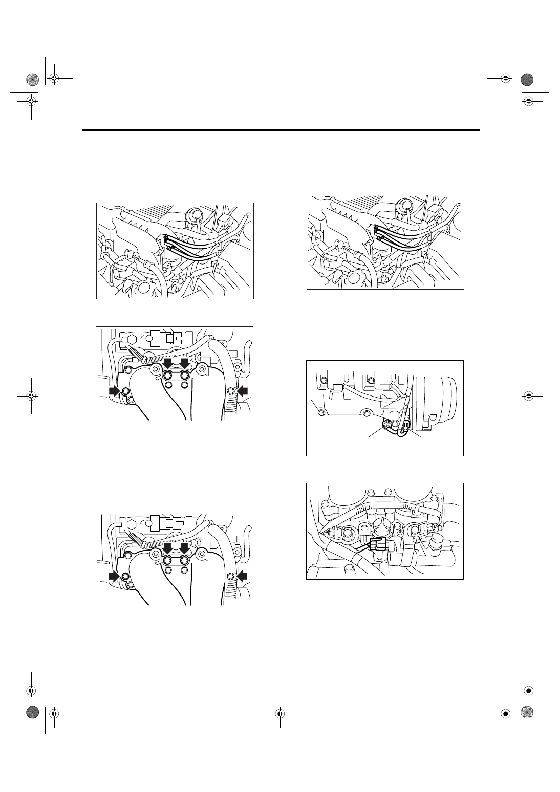
21) Disconnect the connector from ignition coil.
22) Remove the engine harness bracket from rock-
er cover.
(A)
(B)
(C)
FU-00027
FU-01164
FU-01165
FU-01166
FU-01167
(A)
(B)
IG-00092
FU-02155
FU(H4DOTC)-14
FUEL INJECTION (FUEL SYSTEMS)
Intake Manifold
23) Disconnect the fuel delivery hose, return hose
and evaporation hose.
CAUTION:
• Be careful not to spill fuel.
• Catch the fuel from hoses using a container
or cloth.
24) Remove the bolts which hold intake manifold
onto cylinder heads.
25) Remove the intake manifold.
B: INSTALLATION
1) Install the intake manifold onto cylinder heads.
NOTE:
Use a new gasket.
Tightening torque:
25 N
⋅
m (2.5 kgf-m, 18.4 ft-lb)
2) Connect the fuel delivery hose, return hose and
evaporation hose.
NOTE:
If fuel hoses or clamps are damaged, replace them
with new ones.
3) Tighten the hose clamp screws.
Tightening torque:
1.5 N
⋅
m (0.15 kgf-m, 1.1 ft-lb)
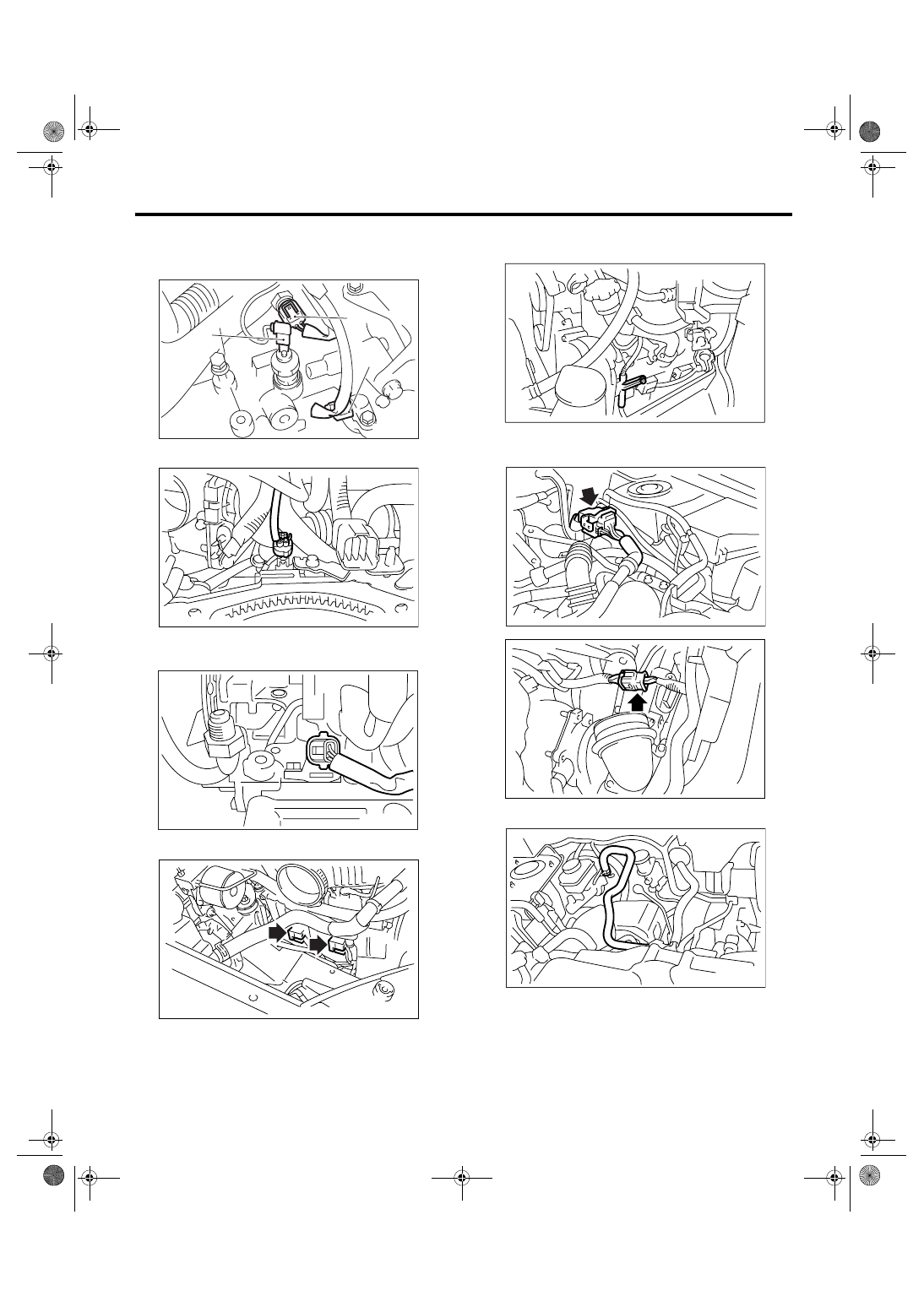
4) Connect the connectors to the exhaust camshaft
position sensor (A) and exhaust oil flow control so-
lenoid valve (B).
5) Connect the connector to intake oil flow control
solenoid valve.
FU-01168
FU-01169
FU-01169
FU-01168
FU-01167
(A)
(B)
FU-01166
FU(H4DOTC)-15
FUEL INJECTION (FUEL SYSTEMS)
Intake Manifold
6) Connect the connectors to the engine coolant
temperature sensor (A), oil pressure switch (B) and
crankshaft position sensor (C).
7) Connect the connector to knock sensor.
8) Connect the connector to intake crankshaft posi-
tion sensor.
9) Connect the connector to ignition coil.
10) Install the engine harness bracket to rocker
cover.
11) Connect the engine harness connectors to
bulkhead harness connectors.
12) Connect the brake booster hose.
(A)
(B)
(C)
FU-00027
FU-01164
FU-01165
IG-00092
FU-02155
FU-01162
FU-01163
FU-01161
FU(H4DOTC)-16
FUEL INJECTION (FUEL SYSTEMS)
Intake Manifold
13) Connect the engine coolant hoses to throttle
body.
14) Connect the PCV hose assembly to cylinder
block.
15) Install the coolant filler tank.
<Ref. to CO(H4DOTC)-31, INSTALLATION, Cool-
ant Filler Tank.>
16) Install the intercooler. <Ref. to IN(H4DOTC)-
12, INSTALLATION, Intercooler.>
17) Install the air cleaner case to intake duct.
18) Install the fuse of fuel pump to main fuse box.
19) Connect the ground cable to battery.
20) Lift-up the vehicle.
21) Install the under cover.
22) Fill engine coolant. <Ref. to CO(H4DOTC)-13,
FILLING OF ENGINE COOLANT, REPLACE-
MENT, Engine Coolant.>
23) Install the collector cover.
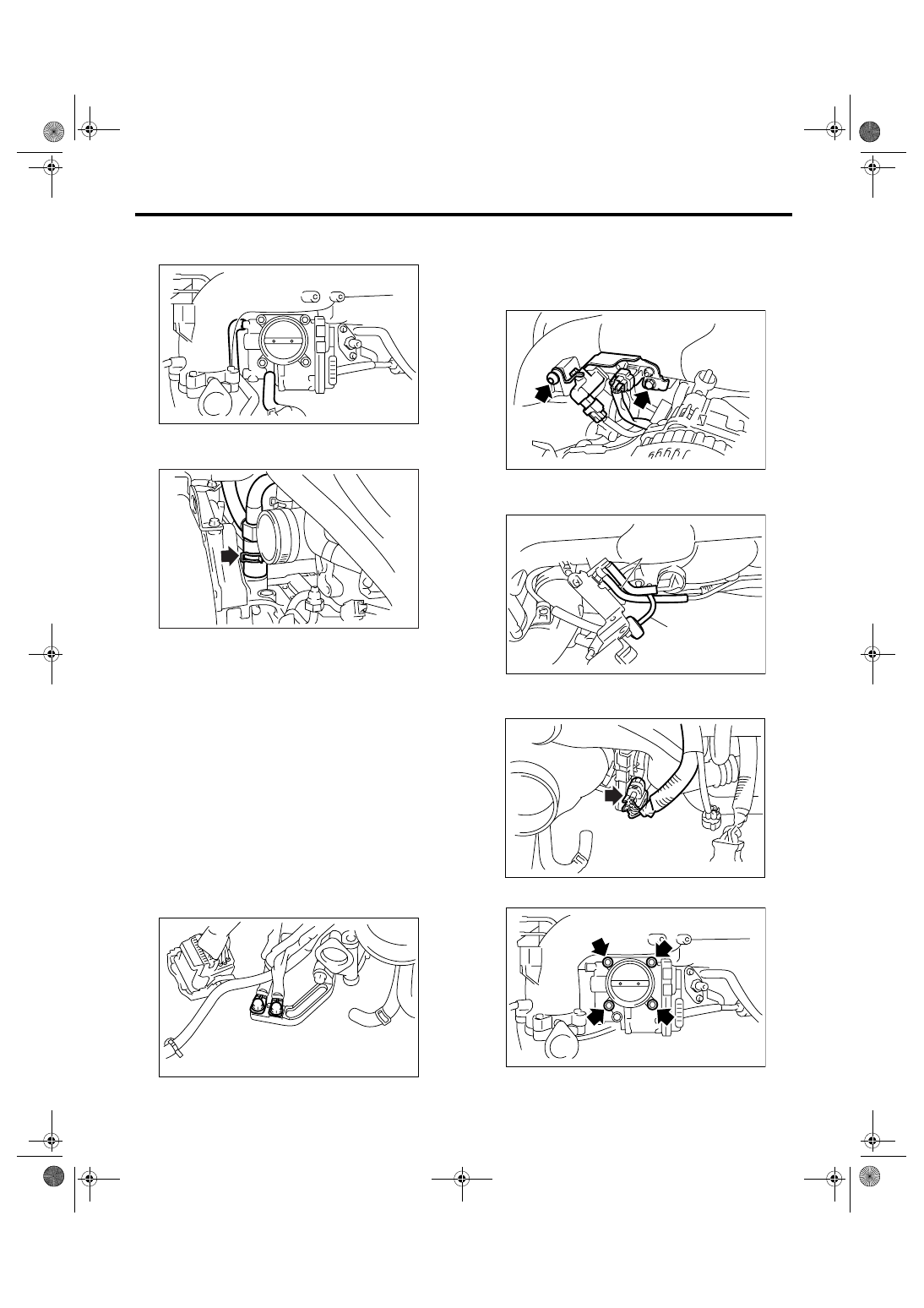
C: DISASSEMBLY
1) Disconnect the engine ground terminal from
ground stay.
2) Remove the solenoid valve bracket assembly
from intake manifold, and disconnect the connector
from the wastegate control solenoid valve, manifold
absolute pressure sensor and purge control sole-
noid valve.
3) Disconnect the evaporation hoses (A) and filter
assembly (B).
4) Disconnect the connector from throttle position
sensor.
5) Remove the throttle body from intake manifold.
FU-01158
FU-01160
FU-01170
EC-00219
FU-01172
(B)
(A)
FU-01157
FU-01159
Нет комментариевНе стесняйтесь поделиться с нами вашим ценным мнением.
Текст