Subaru Legacy (2005 year). Service manual — part 225
EN(H4SO 2.5)(diag)-185
ENGINE (DIAGNOSTICS)
Diagnostic Procedure with Diagnostic Trouble Code (DTC)
8
CHECK HARNESS BETWEEN ECM AND
NEUTRAL POSITION SWITCH CONNEC-
TOR.
1) Disconnect the connector from ECM.
2) Measure the resistance of harness
between ECM and transmission harness con-
nector.
Connector & terminal
(B137) No. 9 — (B25) No. 2:
Is the resistance less than 1
Ω?
Repair the open
circuit of harness
between ECM and
transmission har-
ness connector.
9
CHECK HARNESS BETWEEN ECM AND
NEUTRAL POSITION SWITCH CONNEC-
TOR.
Measure the resistance of harness between
ECM and transmission harness connector.
Connector & terminal
(B25) No. 1 — Engine ground:
Is the resistance less than 5
Ω?
Repair the open
circuit of harness
between ECM and
transmission har-
ness connector.
10
CHECK POOR CONTACT.
Check poor contact in transmission harness
connector.
Is there poor contact in trans-
mission harness connector?
Repair the poor
contact in trans-
mission harness
connector.
Replace the ECM.
<Ref. to FU(H4SO
2.5)-37, Engine
Control Module
(ECM).>
Step
Check
Yes
No
EN(H4SO 2.5)(diag)-186
ENGINE (DIAGNOSTICS)
Diagnostic Procedure with Diagnostic Trouble Code (DTC)
BB:DTC P0852 PARK/NEUTRAL POSITION SWITCH INPUT CIRCUIT HIGH
1. AT MODEL
DTC DETECTING CONDITION:
Detects when malfunction occurs in 2 continuous driving cycles.
TROUBLE SYMPTOM:
Erroneous idling
CAUTION:
After repair or replacement of faulty parts, conduct Clear Memory Mode <Ref. to EN(H4SO 2.5)(diag)-
40, Clear Memory Mode.> and Inspection Mode <Ref. to EN(H4SO 2.5)(diag)-33, Inspection Mode.>.
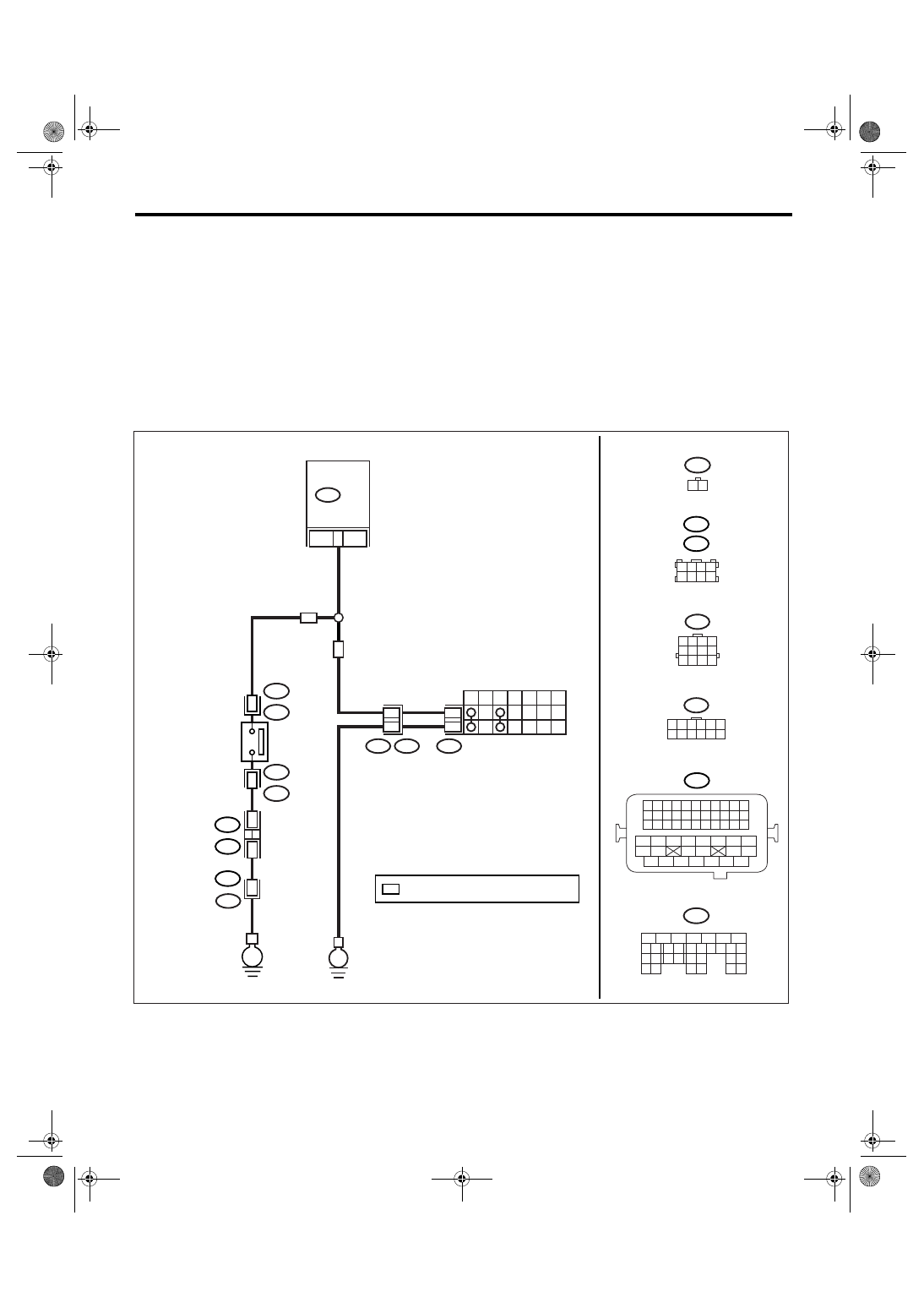
WIRING DIAGRAM:
• EC, EK, EH, ER and K4 model
• KA and KS model
NOTE:
Fuel injection system for KA and KS model is the same as 2.0 L model. Refer to EN(H4SO 2.0) section.
EN-03515
B12
T7
1 2 3 4 5 6
7 8 9 10 11 12
1 2 3 4
5 6 7 8
9 10 11 12
B137
5
6
7
8
2
1
9
4
3
10
22 23
11 12 13 14 15
24 25
26
16 17
18 19 20 21
27
28 29
30 31
B25
1 2
B21
1 2 3 4
12 13 14 15
5 6 7 8
16 17 18 19
9 10 11
20 21 22
23 24 25 26 27 28 29 30 31 32 33
35
34
37
36
39
38
41
40
43
42
44
45
47
46
49
48
51
50
53
52
54
1 2 3 4
5 6 7 8
B122
B138
B12
T3
T7
P
R
N
D
3
2
1
12
7
12
11
B137
9
E
E
1
B25
T2
T2
B25
2
AT
MT
E2
B21
B138
*
*
36
B122
LHD :
RHD :
INHIBITOR SWITCH
ECM
NEUTRAL
POSITION
SWITCH
*
: TERMINAL No. RANDOM ARRANGEMENT
EN(H4SO 2.5)(diag)-187
ENGINE (DIAGNOSTICS)
Diagnostic Procedure with Diagnostic Trouble Code (DTC)
Step
Check
Yes
No
1
CHECK OPTION CODE.
Is the option code EC, EK, EH,
ER or K4?
Refer to EN(H4SO
2.0) section. <Ref.
to EN(H4SO
2.0)(diag)-64, List
of Diagnostic Trou-
ble Code (DTC).>
NOTE:
Fuel injection sys-
tem for KA and KS
model is the same
as 2.0 L model.
2
CHECK ANY OTHER DTC ON DISPLAY.
Is any other DTC displayed?
Check DTC using
“List of Diagnostic
Trouble Code
(DTC)”. <Ref. to
EN(H4SO
2.5)(diag)-69, List
of Diagnostic Trou-
ble Code (DTC).>
3
CHECK INPUT SIGNAL OF ECM.
1) Turn the ignition switch to ON.
2) Measure the voltage between ECM and
chassis ground with select lever at “N” and “P”
range.
Connector & terminal
(B137) No. 9 (+) — Chassis ground (
−
):
Is the voltage less than 1 V?
4
CHECK INPUT SIGNAL OF ECM.
Measure the voltage between ECM and chas-
sis ground with select lever at other than “N”
and “P” range.
Connector & terminal
(B137) No. 9 (+) — Chassis ground (
−
):
Is the voltage more than 10 V? Go to step 5.
5
CHECK POOR CONTACT.
Check poor contact in ECM connector.
Is there poor contact in ECM
connector?
Repair the poor
contact in ECM
connector.
Replace the ECM.
<Ref. to FU(H4SO
2.5)-37, Engine
Control Module
(ECM).>
6
CHECK INPUT SIGNAL OF ECM.
Measure the voltage between ECM and chas-
sis ground.
Connector & terminal
(B137) No. 9 (+) — Chassis ground (
−
):
Is the voltage more than 10 V? Repair the battery
short circuit of har-
ness between
ECM and inhibitor
switch connector.
7
CHECK HARNESS BETWEEN ECM AND IN-
HIBITOR SWITCH CONNECTOR.
1) Turn the ignition switch to OFF.
2) Disconnect the connectors from ECM and
inhibitor switch.
3) Measure the resistance of harness
between ECM and inhibitor switch connector.
Connector & terminal
(B137) No. 9 — (T7) No. 12:
Is the resistance less than 1
Ω?
Repair the har-
ness and connec-
tor.
NOTE:
In this case, repair
the following:
• Open circuit of
harness between
ECM and inhibitor
switch connector
• Poor contact in
coupling connector
• Poor contact in
inhibitor switch
connector
• Poor contact in
ECM connector
EN(H4SO 2.5)(diag)-188
ENGINE (DIAGNOSTICS)
Diagnostic Procedure with Diagnostic Trouble Code (DTC)
8
CHECK INHIBITOR SWITCH GROUND LINE.
Measure the resistance of harness between
inhibitor switch connector and engine ground.
Connector & terminal
(T7) No. 7 — Engine ground:
Is the resistance less than 5
Ω?
Repair the open
circuit of harness
between inhibitor
switch connector
and ground line.
NOTE:
In this case, repair
the following:
• Open circuit of
harness between
inhibitor switch
connector and
ground line
9
CHECK INHIBITOR SWITCH.
Measure the resistance between inhibitor
switch connector receptacle’s terminals with
select lever at “N” and “P” range.
Terminals
(T7) No. 7 — No. 12:
Is the resistance less than 1
Ω?
Replace the inhibi-
tor switch. <Ref. to
4AT-51, Inhibitor
Switch.>
10
CHECK SELECT CABLE CONNECTION.
Is there any fault in select
cable connection to inhibitor
switch?
Repair the select
cable connection.
<Ref. to CS-29,
INSPECTION,
Select Cable.>
Replace the ECM.
<Ref. to FU(H4SO
2.5)-37, Engine
Control Module
(ECM).>
Step
Check
Yes
No
Нет комментариевНе стесняйтесь поделиться с нами вашим ценным мнением.
Текст