Subaru Legacy (2005 year). Service manual — part 328
EN(H4DOTC)(diag)-81
ENGINE (DIAGNOSTICS)
Diagnostic Procedure with Diagnostic Trouble Code (DTC)
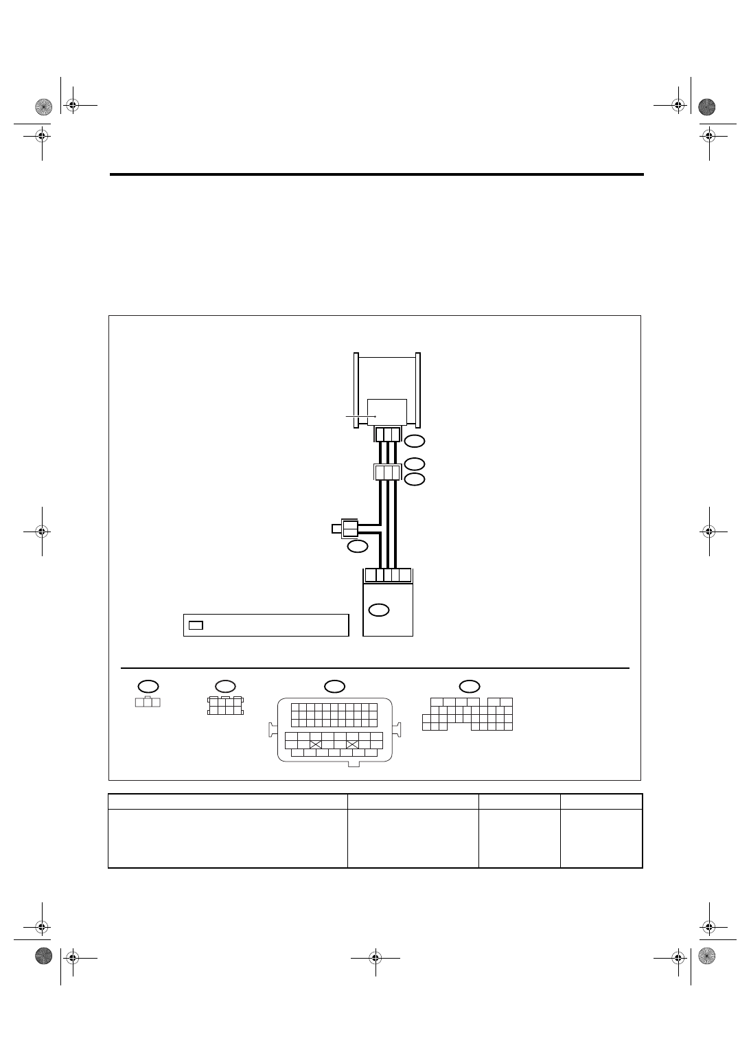
G: DTC P0107 MANIFOLD ABSOLUTE PRESSURE/BAROMETRIC PRESSURE
CIRCUIT LOW INPUT
DTC DETECTING CONDITION:
Immediately at fault recognition
CAUTION:
After repair or replacement of faulty parts, perform Clear Memory Mode <Ref. to EN(H4DOTC)(diag)-
37, OPERATION, Clear Memory Mode.> and Inspection Mode <Ref. to EN(H4DOTC)(diag)-30, PROCE-
DURE, Inspection Mode.>.
WIRING DIAGRAM:
Step
Check
Yes
No
1
CHECK INPUT SIGNAL OF ECM.
Measure the voltage between ECM connector
and chassis ground.
Connector & terminal
(B136) No. 16 (+) — Chassis ground (
−
):
Is the voltage more than 4.5 V? Go to step 3.
B83
3
1
2
35
16
22
ECM
B136
E21
E2
B21
*
*
20
19
7
1 2 3
B21
E21
B136
1 2 3 4
5 6 7 8
B83
EN-01949
5
6
7 8
2
1
9
4
3
10
24
22 23
25
11 12 13 14 15
26 27
28
16
17 18 19 20 21
33 34
29
32
30
31
35
MANIFOLD ABSOLUTE
PRESSURE SENSOR
1 2 3 4
12 13 14 15
5 6 7 8
16 17 18 19
9 10 11
20 21 22
23 24 25 26 27 28 29 30 31 32 33
35
34
37
36
39
38
41
40
43
42
44
45
47
46
49
48
51
50
53
52
54
*
: TERMINAL NO. RANDOM ARRANGEMENT

EN(H4DOTC)(diag)-82
ENGINE (DIAGNOSTICS)
Diagnostic Procedure with Diagnostic Trouble Code (DTC)
2
CHECK INPUT SIGNAL OF ECM.
Measure the voltage between ECM connector
and chassis ground.
Connector & terminal
(B136) No. 16 (+) — Chassis ground (
−
):
Does the voltage change by
shaking the harness and con-
nector of ECM while monitor-
ing the value with voltage
meter?
Repair the poor
contact in ECM
connector.
Replace the ECM.
<Ref. to
FU(H4DOTC)-34,
Engine Control
Module (ECM).>
3
CHECK INPUT SIGNAL OF ECM.
Measure the voltage between ECM and chas-
sis ground.
Connector & terminal
(B136) No. 22 (+) — Chassis ground (
−
):
Is the voltage less than 0.7 V? Go to step 4.
Replace the ECM.
<Ref. to
FU(H4DOTC)-34,
Engine Control
Module (ECM).>
4
CHECK HARNESS BETWEEN ECM AND
MANIFOLD ABSOLUTE PRESSURE SEN-
SOR CONNECTOR.
1) Turn the ignition switch to OFF.
2) Disconnect the connector from manifold
absolute pressure sensor.
3) Turn the ignition switch to ON.
4) Measure the voltage between manifold
absolute pressure sensor connector and
engine ground.
Connector & terminal
(E21) No. 3 (+) — Engine ground (
−
):
Is the voltage more than 4.5 V? Go to step 5.
Repair the open
circuit of harness
between ECM and
manifold absolute
pressure sensor
connector.
5
CHECK HARNESS BETWEEN ECM AND
MANIFOLD ABSOLUTE PRESSURE SEN-
SOR CONNECTOR.
1) Turn the ignition switch to OFF.
2) Disconnect the connector from ECM.
3) Measure the resistance of harness
between ECM and manifold absolute pressure
sensor connector.
Connector & terminal
(B136) No. 35 — (E21) No. 1:
Is the resistance less than 1
Ω?
Repair the open
circuit of harness
between ECM and
manifold absolute
pressure sensor
connector.
6
CHECK HARNESS BETWEEN ECM AND
MANIFOLD ABSOLUTE PRESSURE SEN-
SOR CONNECTOR.
Measure the resistance of harness between
manifold absolute pressure sensor connector
and engine ground.
Connector & terminal
(E21) No. 1 — Engine ground:
Is the resistance more than 1
M
Ω?
Repair the ground
short circuit of har-
ness between
ECM and mani-
fold absolute pres-
sure sensor
connector.
7
CHECK POOR CONTACT.
Check poor contact in manifold absolute pres-
sure sensor connector.
Is there poor contact in mani-
fold absolute pressure sensor
connector?
Repair the poor
contact in mani-
fold absolute pres-
sure sensor
connector.
Replace the mani-
fold absolute pres-
sure sensor. <Ref.
to FU(H4DOTC)-
27, Mass Air Flow
and Intake Air
Temperature Sen-
sor.>
Step
Check
Yes
No

EN(H4DOTC)(diag)-83
ENGINE (DIAGNOSTICS)
Diagnostic Procedure with Diagnostic Trouble Code (DTC)
H: DTC P0108 MANIFOLD ABSOLUTE PRESSURE/BAROMETRIC PRESSURE
CIRCUIT HIGH INPUT
DTC DETECTING CONDITION:
Immediately at fault recognition
CAUTION:
After repair or replacement of faulty parts, perform Clear Memory Mode <Ref. to EN(H4DOTC)(diag)-
37, OPERATION, Clear Memory Mode.> and Inspection Mode <Ref. to EN(H4DOTC)(diag)-30, PROCE-
DURE, Inspection Mode.>.
WIRING DIAGRAM:
Step
Check
Yes
No
1
CHECK INPUT SIGNAL OF ECM.
Measure the voltage between ECM connector
and chassis ground.
Connector & terminal
(B136) No. 16 (+) — Chassis ground (
−
):
Is the voltage more than 4.5 V? Go to step 3.
B83
3
1
2
35
16
22
ECM
B136
E21
E2
B21
*
*
20
19
7
1 2 3
B21
E21
B136
1 2 3 4
5 6 7 8
B83
EN-01949
5
6
7 8
2
1
9
4
3
10
24
22 23
25
11 12 13 14 15
26 27
28
16
17 18 19 20 21
33 34
29
32
30
31
35
MANIFOLD ABSOLUTE
PRESSURE SENSOR
1 2 3 4
12 13 14 15
5 6 7 8
16 17 18 19
9 10 11
20 21 22
23 24 25 26 27 28 29 30 31 32 33
35
34
37
36
39
38
41
40
43
42
44
45
47
46
49
48
51
50
53
52
54
*
: TERMINAL NO. RANDOM ARRANGEMENT

EN(H4DOTC)(diag)-84
ENGINE (DIAGNOSTICS)
Diagnostic Procedure with Diagnostic Trouble Code (DTC)
2
CHECK INPUT SIGNAL OF ECM.
Measure the voltage between ECM connector
and chassis ground.
Connector & terminal
(B136) No. 16 (+) — Chassis ground (
−
):
Does the voltage change by
shaking the harness and con-
nector of ECM while monitor-
ing the value with voltage
meter?
Repair the poor
contact in ECM
connector.
Replace the ECM.
<Ref. to
FU(H4DOTC)-34,
Engine Control
Module (ECM).>
3
CHECK INPUT SIGNAL OF ECM.
Measure the voltage between ECM connector
and chassis ground.
Connector & terminal
(B136) No. 22 (+) — Chassis ground (
−
):
Is the voltage more than 4.5 V? Go to step 4.
Replace the ECM.
<Ref. to
FU(H4DOTC)-34,
Engine Control
Module (ECM).>
4
CHECK HARNESS BETWEEN ECM AND
MANIFOLD ABSOLUTE PRESSURE SEN-
SOR CONNECTOR.
1) Turn the ignition switch to OFF.
2) Disconnect the connector from manifold
absolute pressure sensor.
3) Turn the ignition switch to ON.
4) Measure the voltage between manifold
absolute pressure sensor connector and
engine ground.
Connector & terminal
(E21) No. 3 (+) — Engine ground (
−
):
Is the voltage more than 4.5 V? Go to step 5.
Repair the open
circuit of harness
between ECM and
manifold absolute
pressure sensor
connector.
5
CHECK HARNESS BETWEEN ECM AND
MANIFOLD ABSOLUTE PRESSURE SEN-
SOR CONNECTOR.
1) Turn the ignition switch to OFF.
2) Disconnect the connector from ECM.
3) Measure the resistance of harness
between ECM and manifold absolute pressure
sensor connector.
Connector & terminal
(B136) No. 22 — (E21) No. 2:
Is the resistance less than 1
Ω?
Repair the open
circuit of harness
between ECM and
manifold absolute
pressure sensor
connector.
6
CHECK HARNESS BETWEEN ECM AND
MANIFOLD ABSOLUTE PRESSURE SEN-
SOR CONNECTOR.
Measure the resistance of harness between
ECM and manifold absolute pressure sensor
connector.
Connector & terminal
(B136) No. 35 — (E21) No. 1:
Is the resistance less than 1
Ω?
Repair the open
circuit of harness
between ECM and
manifold absolute
pressure sensor
connector.
7
CHECK POOR CONTACT.
Check poor contact in manifold absolute pres-
sure sensor connector.
Is there poor contact in mani-
fold absolute pressure sensor
connector?
Repair the poor
contact in mani-
fold absolute pres-
sure sensor
connector.
Replace the mani-
fold absolute pres-
sure sensor. <Ref.
to FU(H4DOTC)-
28, Manifold Abso-
lute Pressure Sen-
sor.>
Step
Check
Yes
No
Нет комментариевНе стесняйтесь поделиться с нами вашим ценным мнением.
Текст