Subaru Legacy (2005 year). Service manual — part 483
EN(H6DO)(diag)-245
ENGINE (DIAGNOSTICS)
Diagnostic Procedure with Diagnostic Trouble Code (DTC)
CV:DTC P2102 THROTTLE ACTUATOR CONTROL MOTOR CIRCUIT LOW
DTC DETECTING CONDITION:
Immediately at fault recognition
TROUBLE SYMPTOM:
• Erroneous idling
• Poor driving performance
• Engine stalls.
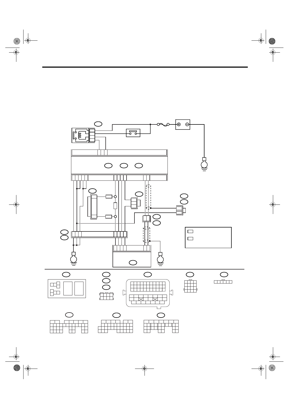
WIRING DIAGRAM:
EN-03499
SBF-7
B135
B:
B137
B136
D:
B362
E1
B20
B83
B122
C:
E
E
E
D6
B35
38
39
20
19
16
15
*
*
E2
B21
E57
4
6
1
2
3
5
D4
D5
C35
C16
B1
B4
D1
D2
D3
36
35
37
C29
C18
ECM
5
6
B362
B20
B21
E57
B122
B83
B138
1 2
7 8
3
4
5
6
1 2 3 4 5 6 7 8 9 10 11
12 13 14 15 16 17 18 19 20 21 22
23 24 25
34 35
36 37 38 39 40 41
48 49
50 51 52 53 54
42 43
44 45
46 47
26 27 28 29 30 31 32 33
1 2 3 4
5 6 7 8
1
2
7
8 9
5
6
3
4
10 11 12
19 20 21
29
30 31
13 14 15 16 17
27
28
18
22 23
24 25
26
1
2
8 9
5
6
3
4
10 11 12
19 20 21
29 30
31
13 14 15 16
17
27
28
18
22 23 24 25 26
7
32 33 34 35
B136
C:
B137
D:
BATTERY
MAIN RELAY
ELECTRONIC
THROTTLE
CONTROL RELAY
ELECTRONIC
THROTTLE CONTROL
1 2 3 4
5 6 7 8
9 10 11 12
13 14 15 16
1 2 3 4 5 6
*
*
1
*
2
*
2
1
1
1
*
1 : TERMINAL No.
RANDOM ARRANGEMENT
B135
5
6
7
8
2
1
9
4
3
10
24
22 23
25
11 12 13 14 15
26 27
28
16 17 18 19
20 21
29 30 31
32 33
34 35
B:
8
7
RHD
RHD
LHD
*
: TERMINAL No.
RANDOM ARRANGEMENT
AMONG 3,4,7, AND 8
2
B122
B138
: LHD
: RHD

EN(H6DO)(diag)-246
ENGINE (DIAGNOSTICS)
Diagnostic Procedure with Diagnostic Trouble Code (DTC)
Step
Check
Yes
No
1
CHECK ELECTRONIC THROTTLE CON-
TROL RELAY.
1) Turn the ignition switch to OFF.
2) Remove the electronic throttle control relay.
3) Connect the battery to electronic throttle
control relay terminals No. 5 and No. 6.
4) Measure the resistance between electronic
throttle control relay terminals.
Terminal
No. 7 — No. 8:
Is the resistance less than 1
Ω?
Replace the elec-
tronic throttle con-
trol relay.
2
CHECK POWER SUPPLY OF ELECTRONIC
THROTTLE CONTROL RELAY.
1) Turn the ignition switch to ON.
2) Measure the voltage between electronic
throttle control relay connector and chassis
ground.
Connector & terminal
(B362) No. 5 (+) — Chassis ground (
−
):
(B362) No. 8 (+) — Chassis ground (
−
):
Is the voltage more than 10 V? Go to step 3.
Repair the open or
ground short cir-
cuit of power sup-
ply circuit.
3
CHECK HARNESS BETWEEN ECM AND
ELECTRONIC THROTTLE CONTROL RE-
LAY.
1) Turn the ignition switch to OFF.
2) Disconnect the connector from ECM.
3) Turn the ignition switch to ON.
4) Measure the voltage between electronic
throttle control relay connector and chassis
ground.
Connector & terminal
(B362) No. 6 (+) — Chassis ground (
−
):
Is the voltage more than 10 V? Repair the power
supply short cir-
cuit of harness
between ECM and
electronic throttle
control relay.
4
CHECK HARNESS BETWEEN ECM AND
ELECTRONIC THROTTLE CONTROL RE-
LAY.
1) Turn the ignition switch to OFF.
2) Measure the resistance between electronic
throttle control relay connector and chassis
ground.
Connector & terminal
(B362) No. 6 — Chassis ground:
(B362) No. 7 — Chassis ground:
Is the resistance more than 1
M
Ω?
Repair the ground
short circuit of har-
ness between
ECM and elec-
tronic throttle con-
trol relay.
5
CHECK HARNESS BETWEEN ECM AND
ELECTRONIC THROTTLE CONTROL RE-
LAY.
Measure the resistance between ECM connec-
tor and electronic throttle control relay connec-
tor.
Connector & terminal
(B135) No. 35 — (B362) No. 6:
(B137) No. 6 — (B362) No. 7:
Is the resistance less than 1
Ω?
Repair the poor
contact in ECM
connector.
Replace the ECM
if defective. <Ref.
to FU(H6DO)-34,
Engine Control
Module (ECM).>
Repair the open
circuit of harness
between ECM and
electronic throttle
control relay.
EN(H6DO)(diag)-247
ENGINE (DIAGNOSTICS)
Diagnostic Procedure with Diagnostic Trouble Code (DTC)
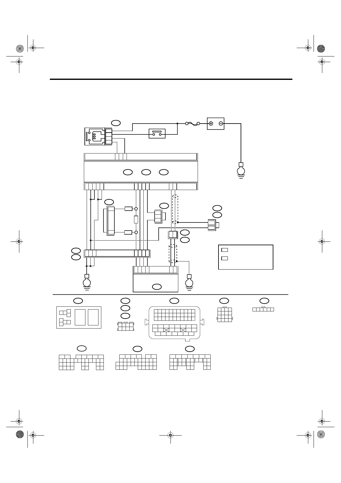
CW:DTC P2103 THROTTLE ACTUATOR CONTROL MOTOR CIRCUIT HIGH
DTC DETECTING CONDITION:
Immediately at fault recognition
WIRING DIAGRAM:
EN-03499
SBF-7
B135
B:
B137
B136
D:
B362
E1
B20
B83
B122
C:
E
E
E
D6
B35
38
39
20
19
16
15
*
*
E2
B21
E57
4
6
1
2
3
5
D4
D5
C35
C16
B1
B4
D1
D2
D3
36
35
37
C29
C18
ECM
5
6
B362
B20
B21
E57
B122
B83
B138
1 2
7 8
3
4
5
6
1 2 3 4 5 6 7 8 9 10 11
12 13 14 15 16 17 18 19 20 21 22
23 24 25
34 35
36 37 38 39 40 41
48 49
50 51 52 53 54
42 43
44 45
46 47
26 27 28 29 30 31 32 33
1 2 3 4
5 6 7 8
1
2
7
8 9
5
6
3
4
10 11 12
19 20 21
29
30 31
13 14 15 16 17
27
28
18
22 23
24 25
26
1
2
8 9
5
6
3
4
10 11 12
19 20 21
29 30
31
13 14 15 16
17
27
28
18
22 23 24 25 26
7
32 33 34 35
B136
C:
B137
D:
BATTERY
MAIN RELAY
ELECTRONIC
THROTTLE
CONTROL RELAY
ELECTRONIC
THROTTLE CONTROL
1 2 3 4
5 6 7 8
9 10 11 12
13 14 15 16
1 2 3 4 5 6
*
*
1
*
2
*
2
1
1
1
*
1 : TERMINAL No.
RANDOM ARRANGEMENT
B135
5
6
7
8
2
1
9
4
3
10
24
22 23
25
11 12 13 14 15
26 27
28
16 17 18 19
20 21
29 30 31
32 33
34 35
B:
8
7
RHD
RHD
LHD
*
: TERMINAL No.
RANDOM ARRANGEMENT
AMONG 3,4,7, AND 8
2
B122
B138
: LHD
: RHD

EN(H6DO)(diag)-248
ENGINE (DIAGNOSTICS)
Diagnostic Procedure with Diagnostic Trouble Code (DTC)
CX:DTC P2109 THROTTLE/PEDAL POSITION SENSOR “A” MINIMUM STOP
PERFORMANCE
NOTE:
For diagnostic procedure, refer to DTC P2101. <Ref. to EN(H6DO)(diag)-239, DTC P2101 THROTTLE AC-
TUATOR CONTROL MOTOR CIRCUIT RANGE/PERFORMANCE, Diagnostic Procedure with Diagnostic
Trouble Code (DTC).>
Step
Check
Yes
No
1
CHECK ELECTRONIC THROTTLE CON-
TROL RELAY.
1) Turn the ignition switch to OFF.
2) Remove the electronic throttle control relay.
3) Measure the resistance between electronic
throttle control relay terminals.
Terminal
No. 7 — No. 8:
Is the resistance more than 1
M
Ω?
Replace the elec-
tronic throttle con-
trol relay.
2
CHECK POWER SUPPLY SHORT CIRCUIT
OF ELECTRONIC THROTTLE CONTROL
RELAY.
1) Turn the ignition switch to ON.
2) Measure the voltage between electronic
throttle control relay connector and chassis
ground.
Connector & terminal
(B362) No. 7 (+) — Chassis ground (
−
):
Is the voltage more than 5 V?
Repair the power
supply short cir-
cuit of harness
between ECM and
electronic throttle
control relay.
3
CHECK HARNESS BETWEEN ECM AND
ELECTRONIC THROTTLE CONTROL RE-
LAY.
1) Turn the ignition switch to OFF.
2) Disconnect the connector from ECM.
3) Measure the resistance between ECM con-
nector and chassis ground.
Connector & terminal
(B135) No. 35 — Chassis ground:
Is the resistance more than 1
M
Ω?
Repair the poor
contact in ECM
connector.
Replace the ECM
if defective. <Ref.
to FU(H6DO)-34,
Engine Control
Module (ECM).>
Repair the ground
short circuit of har-
ness between
ECM and elec-
tronic throttle con-
trol relay.
Нет комментариевНе стесняйтесь поделиться с нами вашим ценным мнением.
Текст