Subaru Legacy (2005 year). Service manual — part 65
ME(H4SO 2.0)-43
MECHANICAL
Timing Belt
15.Timing Belt
A: REMOVAL
1. TIMING BELT
1) Remove the V-belts. <Ref. to ME(H4SO 2.0)-37,
REMOVAL, V-belt.>
2) Remove the crank pulley. <Ref. to ME(H4SO
2.0)-40, REMOVAL, Crank Pulley.>
3) Remove the timing belt cover. <Ref. to
ME(H4SO 2.0)-42, REMOVAL, Timing Belt Cov-
er.>
4) Remove the timing belt guide. (MT model)
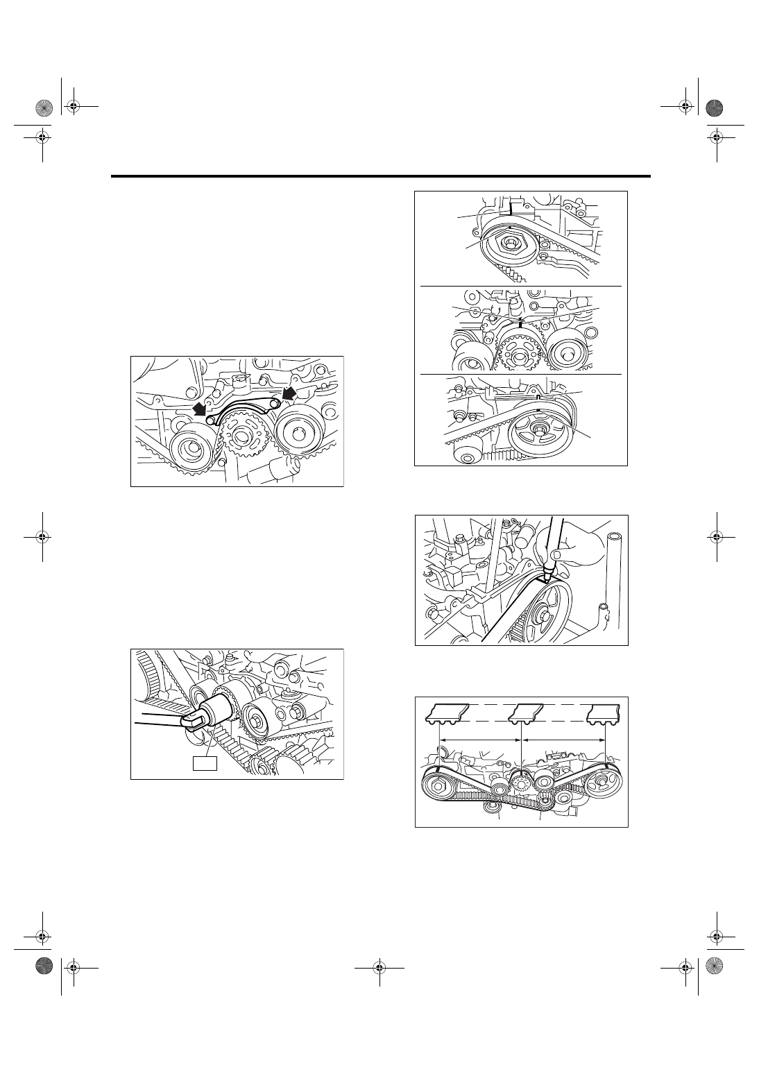
5) If the alignment mark (a) or arrow mark (which
indicates rotation direction) on timing belt fade
away, put new marks before removing the timing
belt as shown in procedures below.
(1) Use the ST to turn crankshaft. Align the
mark (a) of sprocket to the cylinder block notch
(b), and then ensure the adjustments between
right side cam sprocket mark (c) and cam cap
and cylinder head matching surface (d), and be-
tween left side cam sprocket mark (e) and timing
belt cover notch (f) are properly adjusted.
ST
499987500
CRANKSHAFT SOCKET
(2) Using white paint, put an alignment mark or
an arrow mark on the timing belts in relation to
the crank sprocket and cam sprocket.
Specified data:
Z
1
: 46.8 tooth length
Z
2
: 43.7 tooth length
6) Remove the belt idler (No. 2).
ME-00065
ME-00231
ST
(d)
(c)
(a)
(b)
ME-02533
(f)
(e)
ME-00233
ME-00234
Z
1
Z
2
ME(H4SO 2.0)-44
MECHANICAL
Timing Belt
7) Remove the belt idler No. 2.
8) Remove the timing belt.
2. BELT IDLER AND AUTOMATIC BELT
TENSION ADJUSTER ASSEMBLY
1) Remove the belt idler (No. 1).
2) Remove the automatic belt tension adjuster as-
sembly.
B: INSTALLATION
1. AUTOMATIC BELT TENSION ADJUST-
ER ASSEMBLY AND BELT IDLER
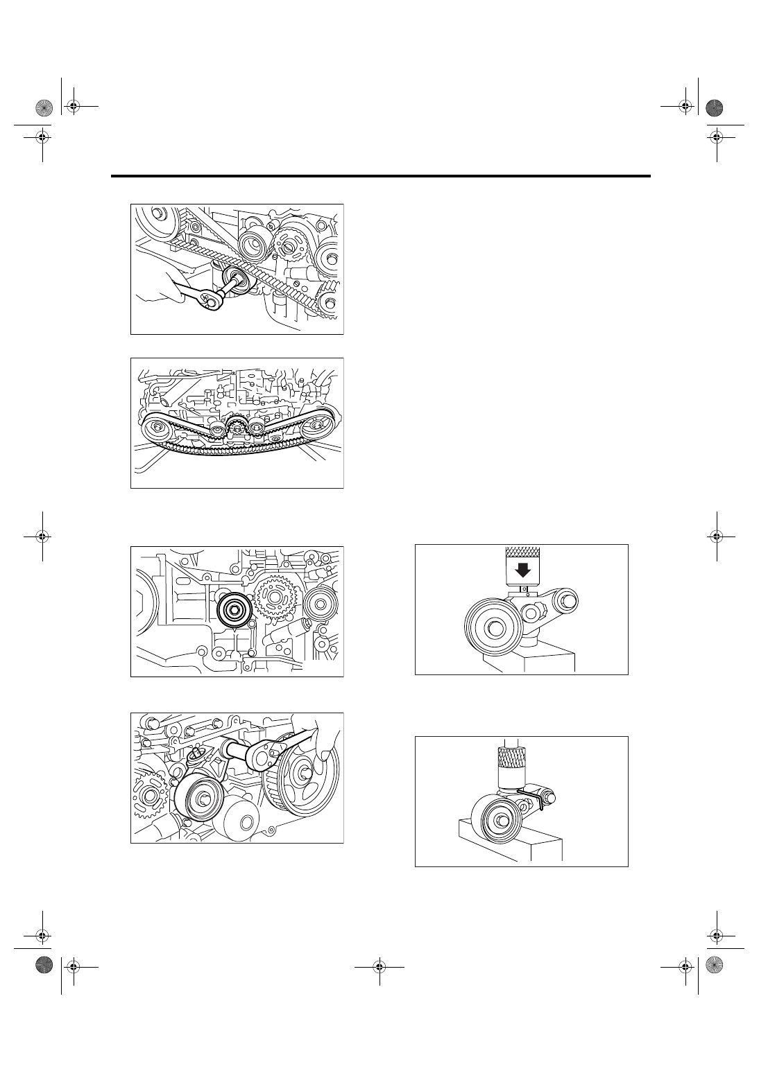
1) Preparation for installation of automatic belt ten-
sion adjuster assembly
CAUTION:
• Always use a vertical type pressing tool to
move the adjuster rod down.
• Do not use a lateral type vise.
• Push the adjuster rod vertically.
• Press-in the push adjuster rod gradually tak-
ing more than three minutes.
• Do not allow press pressure to exceed 9,807
N (1,000 kgf, 2,205 lbf).
• Press the adjuster rod as far as the end sur-
face of the cylinder. Do not press the adjuster
rod into cylinder. Doing so may damage the cyl-
inder.
• Do not release the press pressure before
stopper pin is completely inserted.
(1) Attach the automatic belt tension adjuster
assembly to the vertical pressing tool.
(2) Slowly move the adjuster rod down with a
pressure of 294 N (30 kgf, 66 lbf) or more until
the adjuster rod is aligned with the stopper pin
hole in the cylinder.
(3) With a 2 mm (0.08 in) dia. stopper pin or a 2
mm (nominal) dia. hex wrench inserted into the
stopper pin hole in cylinder, secure the adjuster
rod.
ME-00235
ME-00236
ME-02404
ME-00238
ME-00239
ME-00350
ME(H4SO 2.0)-45
MECHANICAL
Timing Belt
2) Install the automatic belt tension adjuster as-
sembly.
Tightening torque:
39 N
⋅
m (4.0 kgf-m, 28.9 ft-lb)
3) Install the belt idler (No. 1).
Tightening torque:
39 N
⋅
m (4.0 kgf-m, 28.9 ft-lb)
2. TIMING BELT
1) Prepare for installation of automatic belt tension
adjuster assembly. <Ref. to ME(H4SO 2.0)-44, AU-
TOMATIC BELT TENSION ADJUSTER ASSEM-
BLY AND BELT IDLER, INSTALLATION, Timing
Belt.>
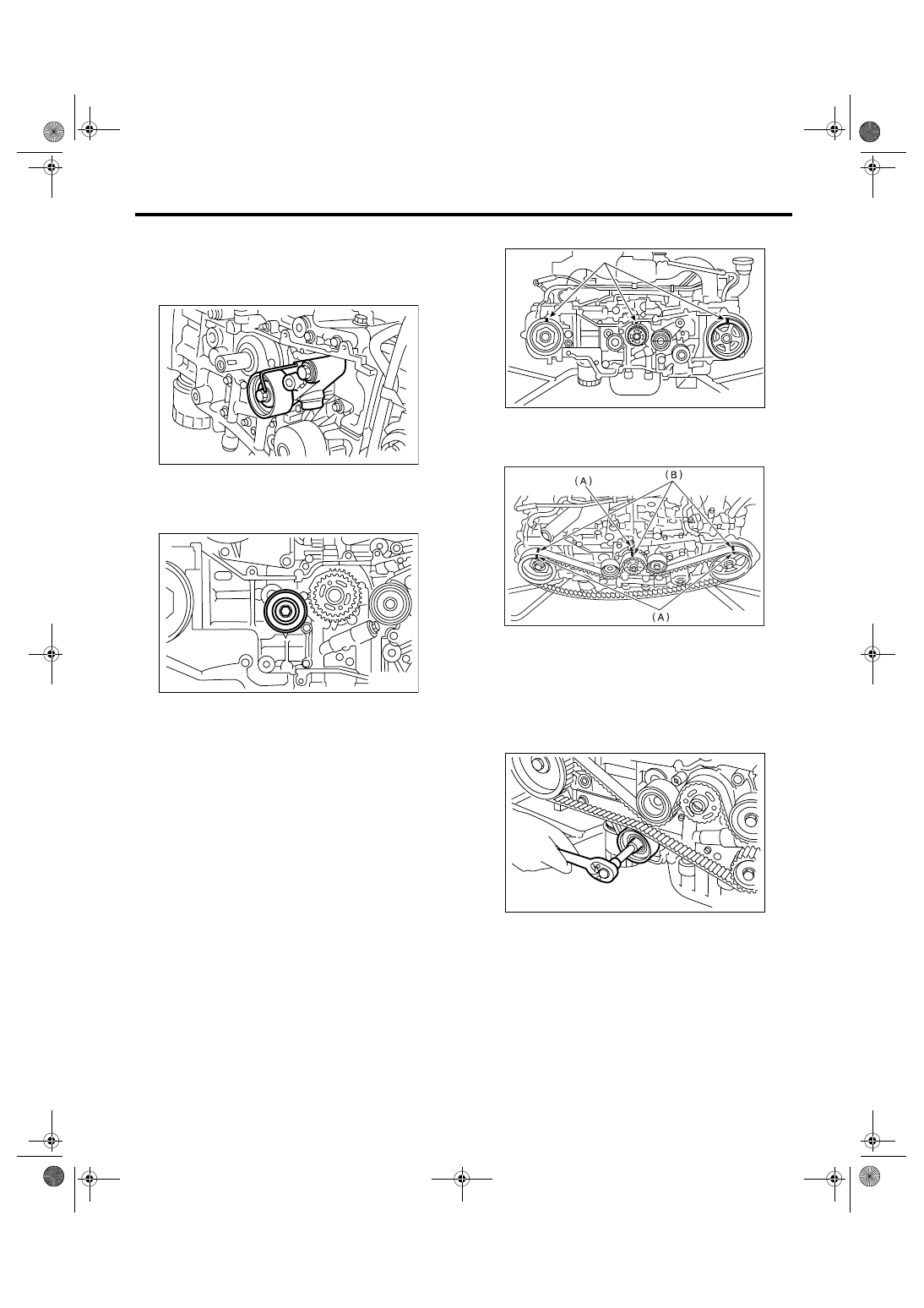
2) Install the timing belt.
(1) Turn the cam sprocket No. 2 using ST1, and
turn the cam sprocket No. 1 using ST2 so that
their alignment marks (A) come to top positions.
ST1
18231AA010 CAM SPROCKET WRENCH
NOTE:
CAM SPROCKET WRENCH (499207100) can
also be used.
ST2
499207400
CAM SPROCKET WRENCH
(2) While aligning alignment marks (B) on the
timing belt with marks (A) on sprockets, position
the timing belt properly.
3) Install the belt idler No. 2.
Tightening torque:
39 N
⋅
m (4.0 kgf-m, 28.9 ft-lb)
4) Install the belt idler (No. 2).
Tightening torque:
39 N
⋅
m (4.0 kgf-m, 28.9 ft-lb)
ME-00241
ME-02404
ME-00243
(A)
ME-00244
ME-00235
ME(H4SO 2.0)-46
MECHANICAL
Timing Belt
5) After ensuring the marks on timing belt and cam
sprockets are aligned, remove the stopper pin from
belt tension adjuster.
6) Install the timing belt guide. (MT model)
(1) Temporarily tighten the timing belt guide
mounting bolts.
(2) Check and adjust the clearance between
timing belt and timing belt guide by using thick-
ness gauge.
Clearance:
1.0
±
0.5 mm (0.039
±
0.020 in)
(3) Tighten the timing belt guide mounting bolts.
Tightening torque:
10 N
⋅
m (1.0 kgf-m, 7.4 ft-lb)
7) Install the timing belt cover.
<Ref. to ME(H4SO 2.0)-42, INSTALLATION, Tim-
ing Belt Cover.>
8) Install the crank pulley. <Ref. to ME(H4SO 2.0)-
40, INSTALLATION, Crank Pulley.>
9) Install the V-belts. <Ref. to ME(H4SO 2.0)-37,
INSTALLATION, V-belt.>
C: INSPECTION
1. TIMING BELT
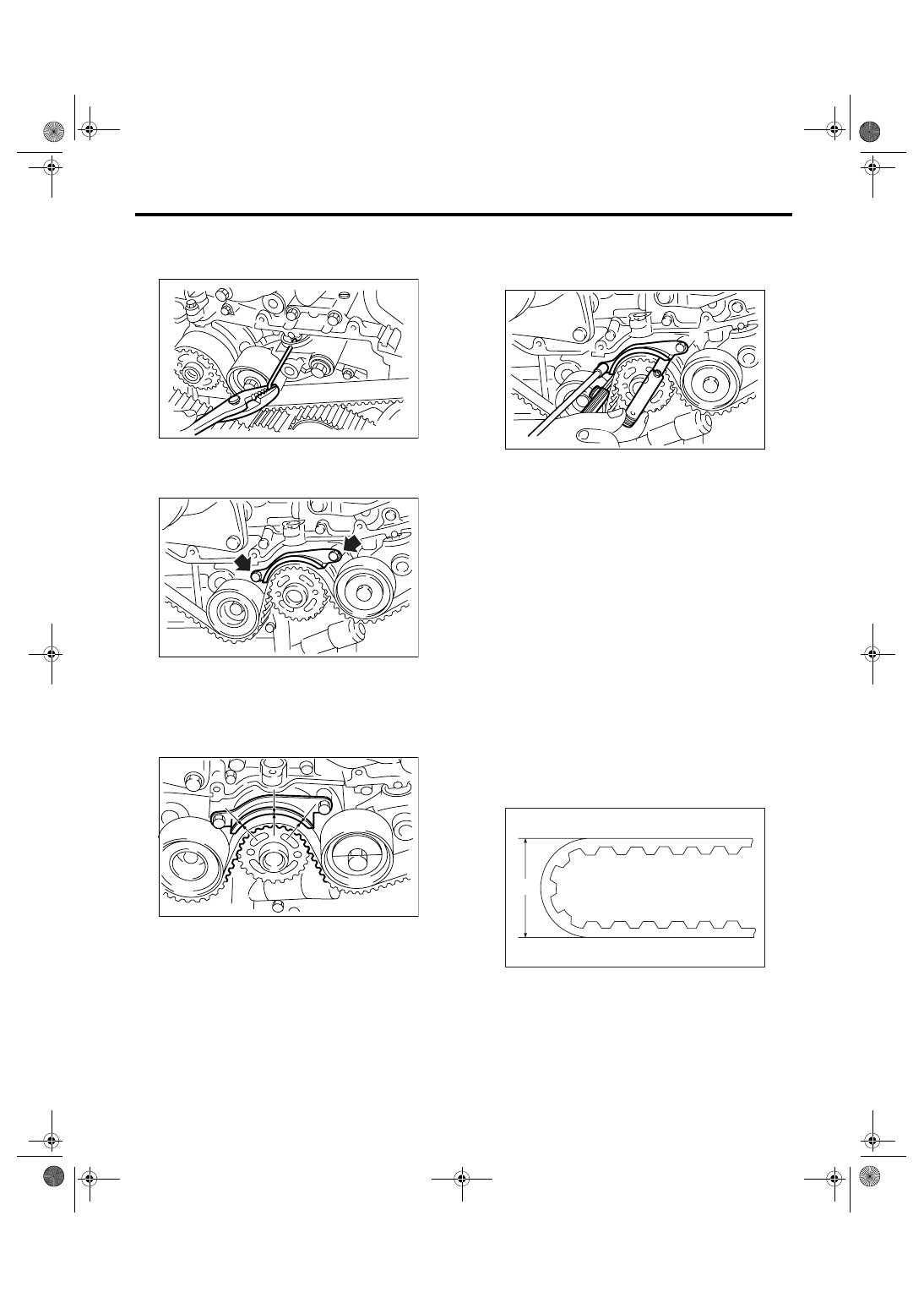
1) Check the timing belt teeth for breaks, cracks or
wear. If any fault is found, replace the belt.
2) Check the condition of the backside of belt. If
cracks are found, replace the belt.
CAUTION:
• Be careful not to let oil, grease or coolant
contact the belt. Remove quickly and thorough-
ly if this happens.
• Do not bend the timing belt sharply.
In radial diameter h:
60 mm (2.36 in) or more
ME-00245
ME-00230
ME-00246
ME-00247
ME-00248
h
Нет комментариевНе стесняйтесь поделиться с нами вашим ценным мнением.
Текст