Subaru Legacy (2005 year). Service manual — part 388
ME(H6DO)-27
MECHANICAL
Fuel Pressure
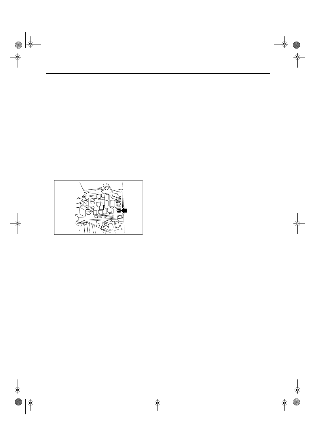
7. Fuel Pressure
A: INSPECTION
WARNING:
Before removing the fuel pressure gauge, re-
lease the fuel pressure.
NOTE:
When the fuel pressure is out of standard, check or
replace the pressure regulator and pressure regu-
lator vacuum hose.
1) Release the fuel pressure.
<Ref. to FU(H6DO)-39, RELEASING OF FUEL
PRESSURE, PROCEDURE, Fuel.>
2) Open the fuel filler flap lid, and remove the fuel
filler cap.
3) Disconnect the fuel delivery hose and connect
fuel pressure gauge.
4) Install the fuse of fuel pump to main fuse box.
5) Start the engine.
6) Measure the fuel pressure while disconnecting
pressure regulator vacuum hose from intake mani-
fold.
Fuel pressure:
Standard: 333 — 363 kPa (3.4 — 3.7 kgf/cm
2
,
48 — 53 psi)
7) After connecting the pressure regulator vacuum
hose, measure the fuel pressure.
Fuel pressure:
Standard: 279 — 309 kPa (2.85 — 3.15 kgf/
cm
2
, 40 — 45 psi)
NOTE:
The fuel pressure gauge indicates 10 to 20 kPa
(0.1 to 0.2 kgf/cm
2
, 1 to 3 psi) higher than standard
during high-altitude operations.
FU-01122
ME(H6DO)-28
MECHANICAL
Valve Clearance
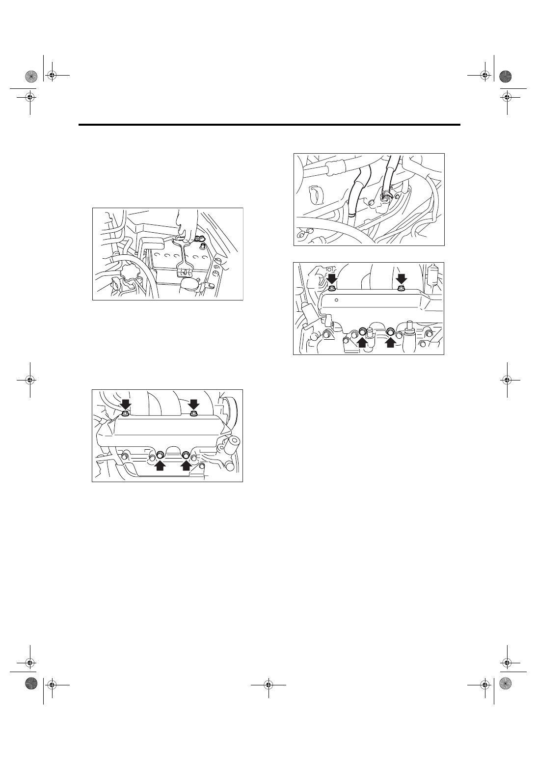
8. Valve Clearance
A: INSPECTION
Inspection and adjustment of valve clearance
should be performed while engine is cold.
1) Set the vehicle on a lift.
2) Remove the collector cover.
3) Disconnect the ground cable from battery.
4) Lift-up the vehicle.
5) Remove the under cover.
6) Lower the vehicle.
7) When inspecting RH side cylinders:
(1) Remove the air intake duct and air cleaner
case. <Ref. to IN(H6DO)-8, REMOVAL, Air In-
take Duct.> <Ref. to IN(H6DO)-5, REMOVAL,
Air Cleaner Case.>
(2) Remove the fuel tank protector (RH).
(3) Disconnect the connector of oil pressure
switch.
(4) Remove the ignition coil. <Ref. to
IG(H6DO)-7, REMOVAL, Ignition Coil.>
(5) Remove the rocker cover (RH).
8) When inspecting LH side cylinders:
(1) Disconnect the battery cable, and then re-
move the battery and battery carrier.
(2) Disconnect the PCV hose and blow-by hose
from rocker cover (LH).
(3) Remove the fuel pipe protector (LH).
(4) Remove the ignition coil. <Ref. to
IG(H6DO)-7, REMOVAL, Ignition Coil.>
(5) Remove the rocker cover (LH).
IN-00203
FU-02119
ME-00460
FU-02117
ME(H6DO)-29
MECHANICAL
Valve Clearance
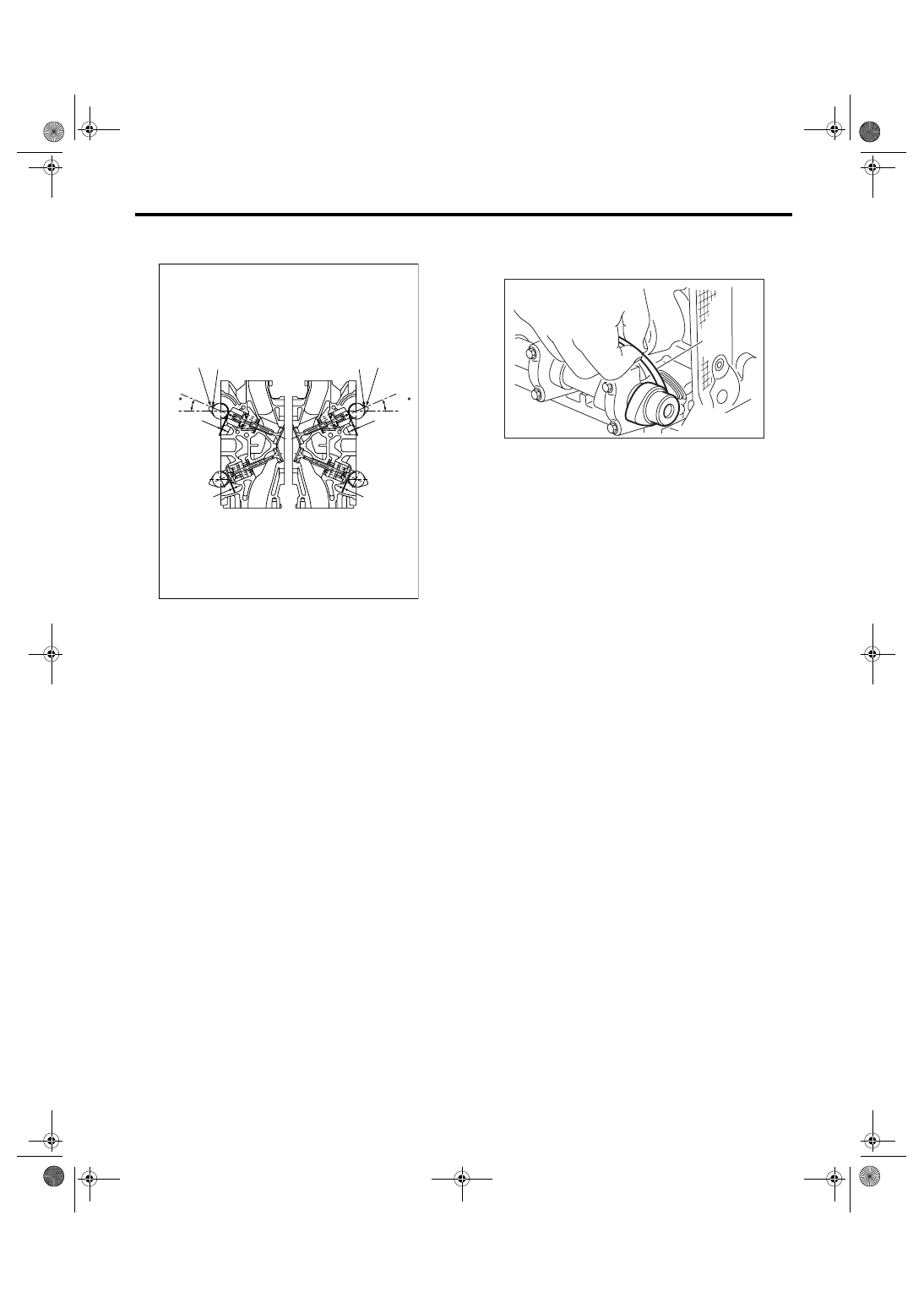
9) Turn the crankshaft clockwise until the cam is
set to position shown in the figure.
10) Measure the clearance of intake valve and ex-
haust valve using thickness gauge (A).
NOTE:
• Measure it within the range of
±30° for specified
position that shown in the figure.
• Measure it in low lift cam for intake side.
• Insert the thickness gauge in direction as hori-
zontal as possible with respect to the valve lifter.
Valve clearance:
Intake
0.20
+0.04
−0.06
mm (0.0079
+0.0016
−0.0024
in)
Exhaust
0.35
±
0.05 mm (0.0138
±
0.0020 in)
• If the measured value is not within standard, take
notes of the value in order to adjust the valve clear-
ance later on.
11) If necessary, adjust the valve clearance. <Ref.
to ME(H6DO)-29, ADJUSTMENT, Valve Clear-
ance.>
12) Further turn the crank pulley clockwise and
then measure the valve clearances again.
13) After inspection, install the related parts in the
reverse order of removal.
B: ADJUSTMENT
1. INTAKE SIDE
CAUTION:
• Adjustment of valve clearance should be per-
formed while engine is cold.
• Do not wear gloves during removal and in-
stallation of valve lifter.
• Do not use the valve lifter which got high im-
pact due to drop, etc.
• When installing the valve lifter, align the anti-
rotation of valve lifter with groove on cylinder
head, and then insert the valve lifter.
1) Measure all valve clearances.
<Ref. to ME(H6DO)-28, INSPECTION, Valve
Clearance.>
NOTE:
Record each valve clearance after it has been
measured.
2) Remove the camshaft. <Ref. to ME(H6DO)-56,
REMOVAL, Camshaft.>
3) Remove the valve lifter.
4) Remove the shim from valve lifter.
5) Check the thickness of shim by stamped mark
on the side of shim which is removed.
(1) Valve clearance (Intake side)
(2) Valve clearance (Exhaust side)
(3) High lift cam
(4) Low lift cam
ME-02565
(4)
(3)
(3)
(4)
(1)
(2)
(1)
(2)
(23 )
(23 )
(A)
ME-00464
ME(H6DO)-30
MECHANICAL
Valve Clearance
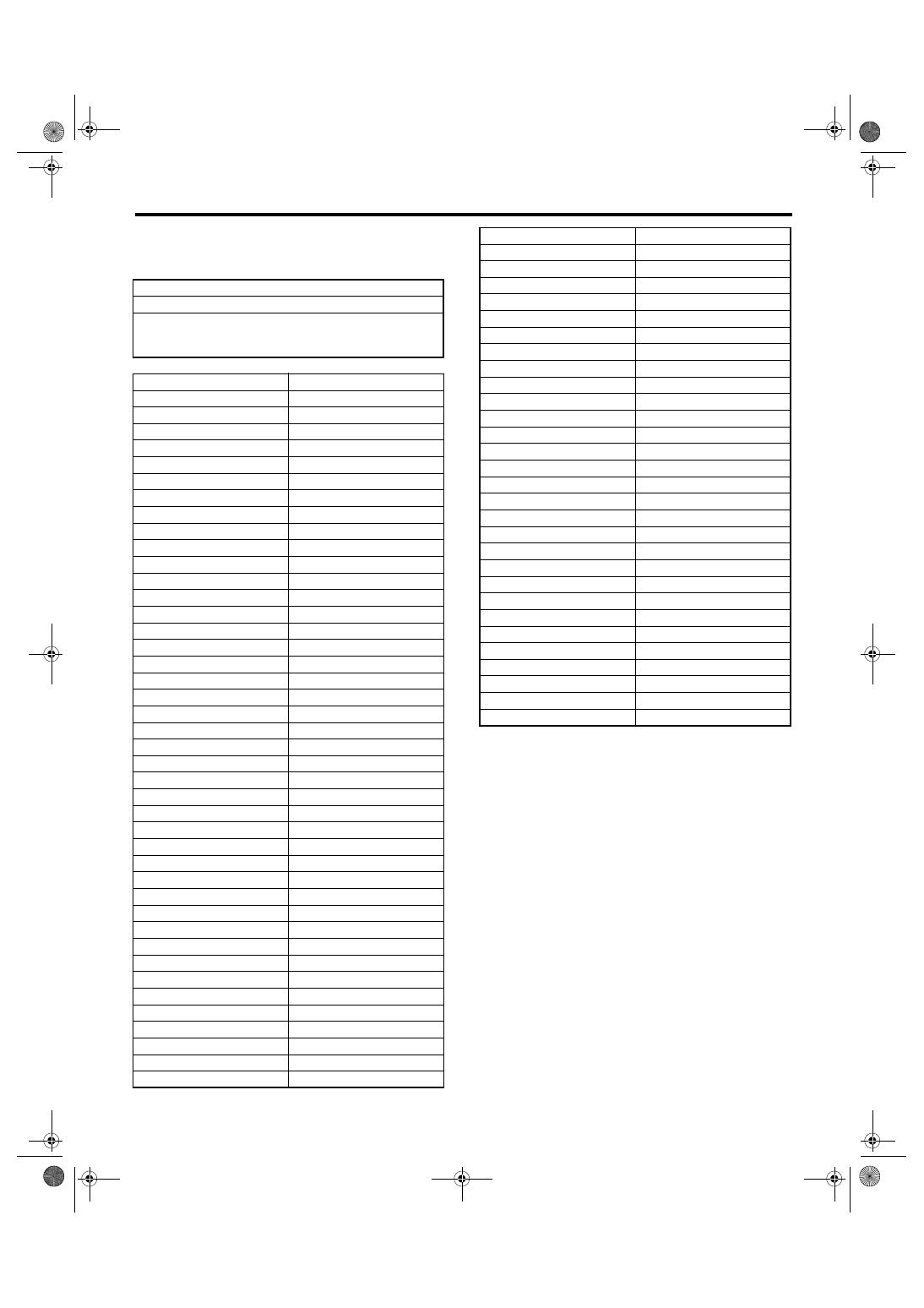
6) Select a shim of suitable thickness from the fol-
lowing table using the measured valve clearance
and shim thickness.
2. EXHAUST SIDE
CAUTION:
• Adjustment of valve clearance should be per-
formed while engine is cold.
• Do not wear gloves during removal and in-
stallation of valve lifter.
• Do not use the valve lifter which got high im-
pact due to drop, etc.
1) Measure all valve clearances.
<Ref. to ME(H6DO)-28, INSPECTION, Valve
Clearance.>
NOTE:
Record each valve clearance after it has been
measured.
2) Remove the camshaft. <Ref. to ME(H6DO)-56,
REMOVAL, Camshaft.>
3) Remove the valve lifter.
Unit: (mm)
S = (V + T)
− 0.20
S: Required shim thickness
V: Measured valve clearance
T: Shim thickness to be used
Part No.
Thickness mm (in)
13218AK890
1.92 (0.0756)
13218AK900
1.94 (0.0764)
13218AK910
1.96 (0.0772)
13218AK920
1.98 (0.0780)
13218AK930
2.00 (0.0787)
13218AK940
2.02 (0.0795)
13218AK950
2.04 (0.0803)
13218AK960
2.06 (0.0811)
13218AK970
2.07 (0.0815)
13218AK980
2.08 (0.0819)
13218AK990
2.09 (0.0823)
13218AL000
2.10 (0.0827)
13218AL010
2.11 (0.0831)
13218AL020
2.12 (0.0835)
13218AL030
2.13 (0.0839)
13218AL040
2.14 (0.0843)
13218AL050
2.15 (0.0846)
13218AL060
2.16 (0.0850)
13218AL070
2.17 (0.0854)
13218AL080
2.18 (0.0858)
13218AL090
2.19 (0.0862)
13218AL100
2.20 (0.0866)
13218AL110
2.21 (0.0870)
13218AL120
2.22 (0.0874)
13218AL130
2.23 (0.0878)
13218AL140
2.24 (0.0882)
13218AL150
2.25 (0.0886)
13218AL160
2.26 (0.0890)
13218AL170
2.27 (0.0894)
13218AL180
2.28 (0.0898)
13218AL190
2.29 (0.0902)
13218AL200
2.30 (0.0906)
13218AL210
2.31 (0.0909)
13218AL220
2.32 (0.0913)
13218AL230
2.33 (0.0917)
13218AL240
2.34 (0.0921)
13218AL250
2.35 (0.0925)
13218AL260
2.36 (0.0929)
13218AL270
2.37 (0.0933)
13218AL280
2.38 (0.0937)
13218AL290
2.39 (0.0941)
13218AL300
2.40 (0.0945)
13218AL310
2.41 (0.0949)
13218AL320
2.42 (0.0953)
13218AL330
2.43 (0.0957)
13218AL340
2.44 (0.0961)
13218AL350
2.45 (0.0965)
13218AL360
2.46 (0.0969)
13218AL370
2.47 (0.0972)
13218AL380
2.48 (0.0976)
13218AL390
2.49 (0.0980)
13218AL400
2.50 (0.0984)
13218AL410
2.51 (0.0988)
13218AL420
2.52 (0.0992)
13218AL430
2.53 (0.0996)
13218AL440
2.54 (0.1000)
13218AL450
2.55 (0.1004)
13218AL460
2.56 (0.1008)
13218AL470
2.57 (0.1012)
13218AL480
2.58 (0.1016)
13218AL490
2.59 (0.1020)
13218AL500
2.60 (0.1024)
13218AL510
2.61 (0.1028)
13218AL520
2.62 (0.1032)
13218AL530
2.64 (0.1039)
13218AL540
2.66 (0.1047)
13218AL550
2.68 (0.1055)
13218AL560
2.70 (0.1063)
13218AL570
2.72 (0.1071)
13218AL580
2.74 (0.1079)
13218AL590
2.76 (0.1087)
Part No.
Thickness mm (in)
Нет комментариевНе стесняйтесь поделиться с нами вашим ценным мнением.
Текст