Subaru Legacy (2005 year). Service manual — part 389
ME(H6DO)-31
MECHANICAL
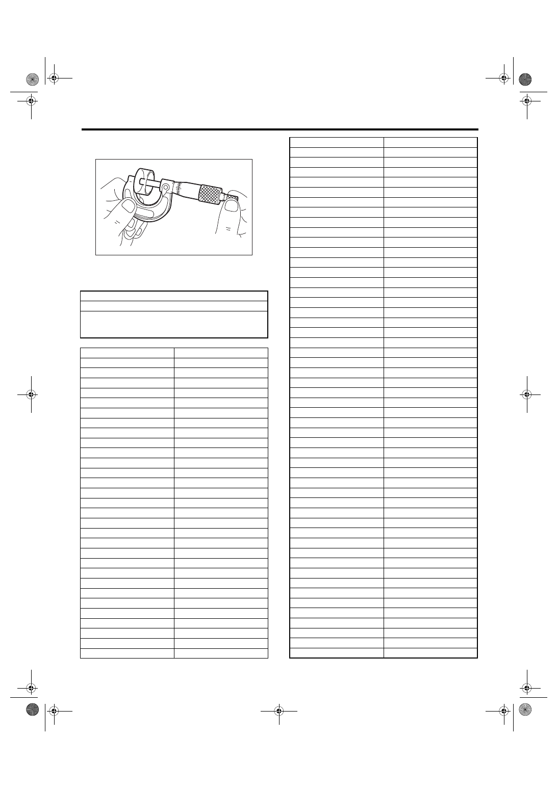
Valve Clearance
4) Measure the thickness of valve lifter using a mi-
crometer.
5) Select a valve lifter of suitable thickness from the
following table using the measured valve clearance
and valve lifter thickness.
Unit: (mm)
S = (V + T)
− 0.35
S: Valve lifter thickness required
V: Measured valve clearance
T: Valve lifter thickness to be used
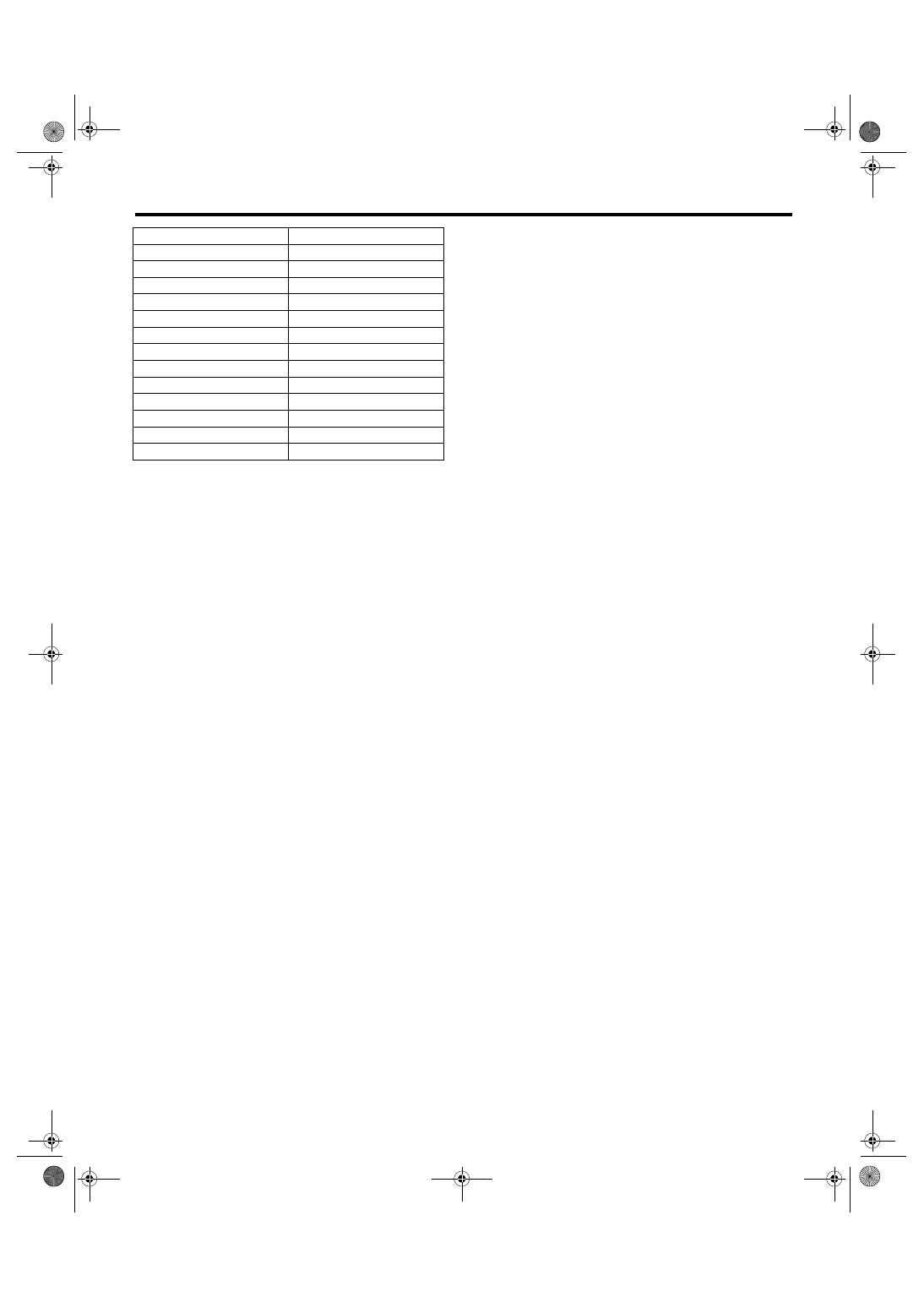
Part No.
Thickness mm (in)
13228AD180
4.32 (0.1701)
13228AD190
4.34 (0.1709)
13228AD200
4.36 (0.1717)
13228AD210
4.38 (0.1724)
13228AD220
4.40 (0.1732)
13228AD230
4.42 (0.1740)
13228AD240
4.44 (0.1748)
13228AD250
4.46 (0.1756)
13228AD260
4.48 (0.1764)
13228AD270
4.50 (0.1772)
13228AD280
4.52 (0.1780)
13228AD290
4.54 (0.1787)
13228AD300
4.56 (0.1795)
13228AD310
4.58 (0.1803)
13228AD320
4.60 (0.1811)
13228AC580
4.62 (0.1819)
13228AC590
4.63 (0.1823)
13228AC600
4.64 (0.1827)
13228AC610
4.65 (0.1831)
13228AC620
4.66 (0.1835)
13228AC630
4.67 (0.1839)
13228AC640
4.68 (0.1843)
13228AC650
4.69 (0.1846)
13228AC660
4.70 (0.1850)
13228AC670
4.71 (0.1854)
13228AC680
4.72 (0.1858)
13228AC690
4.73 (0.1862)
13228AC700
4.74 (0.1866)
13228AC710
4.75 (0.1870)
13228AC720
4.76 (0.1874)
ME-00025
13228AC730
4.77 (0.1878)
13228AC740
4.78 (0.1882)
13228AC750
4.79 (0.1886)
13228AC760
4.80 (0.1890)
13228AC770
4.81 (0.1894)
13228AC780
4.82 (0.1898)
13228AC790
4.83 (0.1902)
13228AC800
4.84 (0.1906)
13228AC810
4.85 (0.1909)
13228AC820
4.86 (0.1913)
13228AC830
4.87 (0.1917)
13228AC840
4.88 (0.1921)
13228AC850
4.89 (0.1925)
13228AC860
4.90 (0.1929)
13228AC870
4.91 (0.1933)
13228AC880
4.92 (0.1937)
13228AC890
4.93 (0.1941)
13228AC900
4.94 (0.1945)
13228AC910
4.95 (0.1949)
13228AC920
4.96 (0.1953)
13228AC930
4.97 (0.1957)
13228AC940
4.98 (0.1961)
13228AC950
4.99 (0.1965)
13228AC960
5.00 (0.1969)
13228AC970
5.01 (0.1972)
13228AC980
5.02 (0.1976)
13228AC990
5.03 (0.1980)
13228AD000
5.04 (0.1984)
13228AD010
5.05 (0.1988)
13228AD020
5.06 (0.1992)
13228AD030
5.07 (0.1996)
13228AD040
5.08 (0.2000)
13228AD050
5.09 (0.2004)
13228AD060
5.10 (0.2008)
13228AD070
5.11 (0.2012)
13228AD080
5.12 (0.2016)
13228AD090
5.13 (0.2020)
13228AD100
5.14 (0.2024)
13228AD110
5.15 (0.2028)
13228AD120
5.16 (0.2032)
13228AD130
5.17 (0.2035)
13228AD140
5.18 (0.2039)
13228AD150
5.19 (0.2043)
13228AD160
5.20 (0.2047)
13228AD170
5.21 (0.2051)
13228AD330
5.23 (0.2059)
13228AD340
5.25 (0.2067)
13228AD350
5.27 (0.2075)
13228AD360
5.29 (0.2083)
13228AD370
5.31 (0.2091)
13228AD380
5.33 (0.2098)
Part No.
Thickness mm (in)
ME(H6DO)-32
MECHANICAL
Valve Clearance
13228AD390
5.35 (0.2106)
13228AD400
5.37 (0.2114)
13228AD410
5.39 (0.2122)
13228AD420
5.41 (0.2130)
13228AD430
5.43 (0.2138)
13228AD440
5.45 (0.2146)
13228AD450
5.47 (0.2154)
13228AD460
5.49 (0.2161)
13228AD470
5.51 (0.2169)
13228AD480
5.53 (0.2177)
13228AD490
5.55 (0.2185)
13228AD500
5.57 (0.2193)
13228AD510
5.59 (0.2201)
Part No.
Thickness mm (in)
ME(H6DO)-33
MECHANICAL
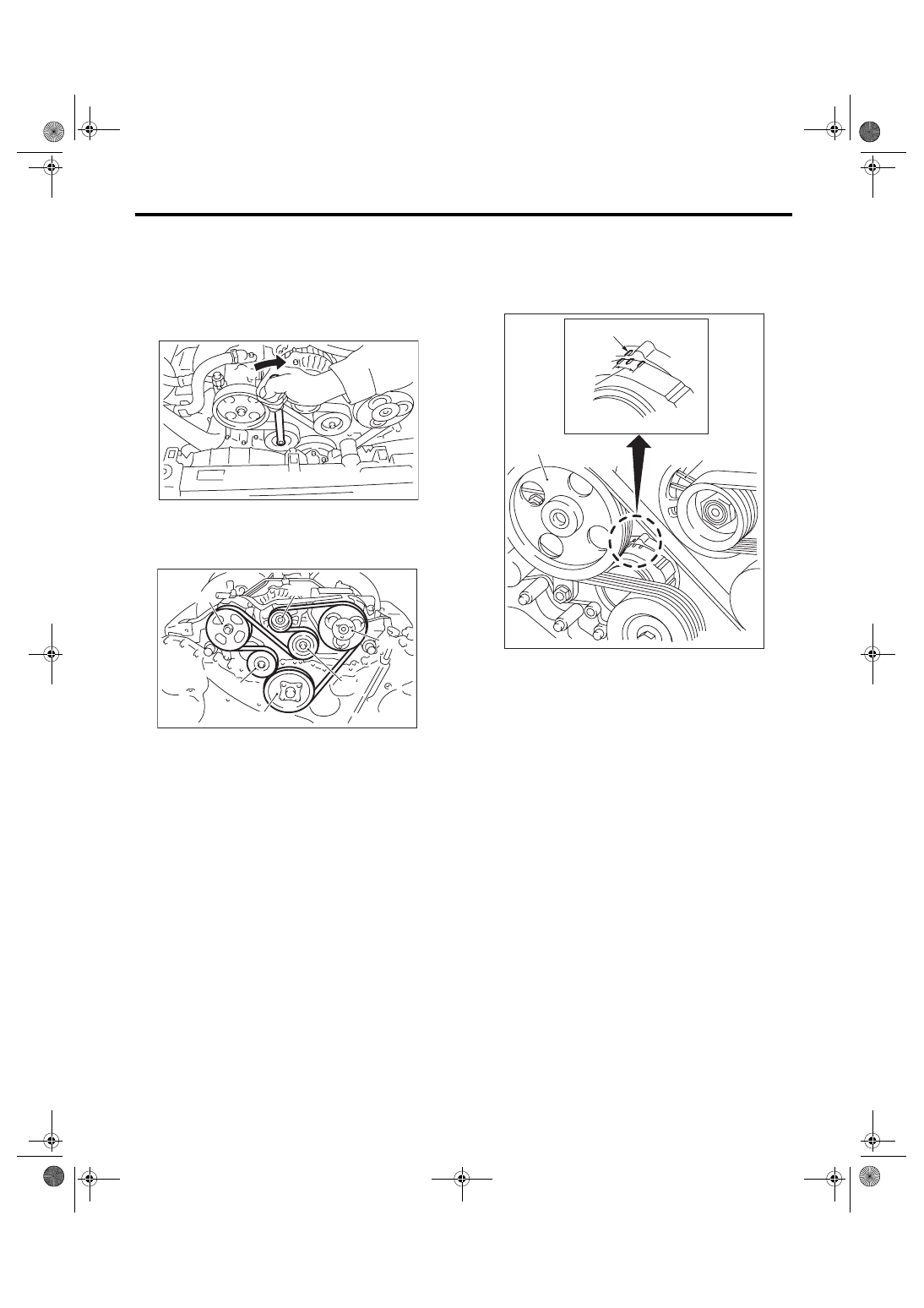
V-belt
9. V-belt
A: REMOVAL
1) Install the tool to belt tension adjuster assembly
installation bolt.
2) Rotate the tool clockwise and loosen the V-belt
to remove.
3) Remove the V-belt cover.
B: INSTALLATION
Install in the reverse order of removal.
C: INSPECTION
1) Replace the V-belt, if cracks, fraying or wear is
found.
2) Make sure that the V-belt automatic belt tension
indicator (A) is within the range (D).
(1) Power steering oil pump pulley
(2) Belt tension adjuster ASSY
(3) Crank pulley
(4) A/C compressor
(5) Belt idler
(6) Generator
ME-00473
(1)
(6)
(4)
(5)
(2)
(3)
ME-00474
(A) Indicator
(B) Generator
(C) Power steering oil pump pulley
(D) Service limit
(B)
(A)
(D)
(C)
ME-00475
ME(H6DO)-34
MECHANICAL
Engine Assembly
10.Engine Assembly
A: REMOVAL
1) Set the vehicle on a lift.
2) Open the front hood fully and support it with front
food stay.
3) Remove the collector cover.
4) Collect the refrigerant from A/C system. <Ref. to
AC-20, PROCEDURE, Refrigerant Recovery Pro-
cedure.>
5) Release the fuel pressure.
<Ref. to FU(H6DO)-39, RELEASING OF FUEL
PRESSURE, PROCEDURE, Fuel.>
6) Remove the fuel filler cap.
7) Disconnect the ground cable from battery.
8) Remove the air intake duct, air cleaner case and
air intake chamber.
<Ref. to IN(H6DO)-8, REMOVAL, Air Intake Duct.>
<Ref. to IN(H6DO)-5, REMOVAL, Air Cleaner
Case.> <Ref. to IN(H6DO)-7, REMOVAL, Air In-
take Chamber.>
9) Remove the radiator from vehicle. <Ref. to
CO(H6DO)-16, REMOVAL, Radiator.>
10) Remove the V-belts. <Ref. to ME(H6DO)-33,
REMOVAL, V-belt.>
11) Disconnect the A/C pressure hoses from A/C
compressor. <Ref. to AC-39, REMOVAL, Hose and
Tube.>
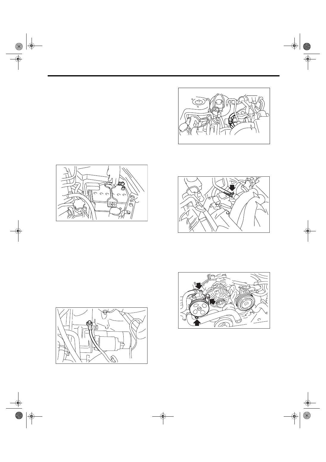
12) Disconnect the following connectors:
(1) Engine ground terminals
(2) Engine harness connectors
(3) Generator connector, terminal and A/C
compressor connector
(4) Power steering switch connector
13) Disconnect the following hoses:
(1) Brake booster vacuum hose
(2) Heater inlet and outlet hoses
(3) Pressure regulator vacuum hose
14) Remove the power steering pump.
NOTE:
Do not disconnect the hose and pipe from pump
body.
IN-00203
ME-00476
(A) Power steering pump
(B) Generator
(C) A/C compressor
ME-02026
FU-02115
(A)
(B)
(C)
ME-02444
Нет комментариевНе стесняйтесь поделиться с нами вашим ценным мнением.
Текст