Subaru Legacy (2005 year). Service manual — part 659
5MT-83
MANUAL TRANSMISSION AND DIFFERENTIAL
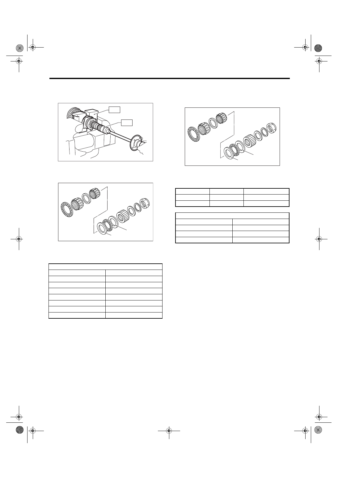
Drive Pinion Shaft Assembly
Starting torque:
0.3 — 0.8 N
⋅
m (0.03 — 0.08 kgf-m, 0.2 — 0.6 ft-
lb)
4) If the starting torque is not within specified limit,
select new adjusting washer No. 1 and recheck
starting torque.
5) When the specified starting torque cannot be ob-
tained by the adjusting washer No. 1, select the ad-
justing washer No. 2 from following table. Repeat
steps 1) through 4) to adjust starting torque.
6) Recheck that the starting torque is within speci-
fied range, then clinch the lock nut at four positions.
(A) Adjusting washer No. 1
(B) Adjusting washer No. 2
Adjusting washer No. 1
Part Number
Thickness mm (in)
803025051
3.925 (0.1545)
803025052
3.950 (0.1555)
803025053
3.975 (0.1565)
803025054
4.000 (0.1575)
803025055
4.025 (0.1585)
803025056
4.050 (0.1594)
803025057
4.075 (0.1604)
MT-00269
ST1
ST3
MT-00270
( A )
( B )
(A) Adjusting washer No. 1
(B) Adjusting washer No. 2
Starting torque
Dimension H
Washer No. 2
Low
Small
Select thicker one.
High
Large
Select thinner one.
Adjusting washer No. 2
Part Number
Thickness mm (in)
803025059
3.850 (0.1516)
803025054
4.000 (0.1575)
803025058
4.150 (0.1634)
MT-00270
( A )
( B )
5MT-84
MANUAL TRANSMISSION AND DIFFERENTIAL
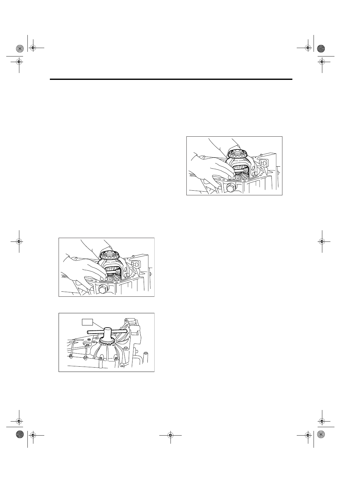
Front Differential Assembly
19.Front Differential Assembly
A: REMOVAL
1) Remove the manual transmission assembly
from vehicle. <Ref. to 5MT-30, REMOVAL, Manual
Transmission Assembly.>
2) Remove the transfer case with extension case
assembly. <Ref. to 5MT-43, REMOVAL, Transfer
Case and Extension Case Assembly.>
3) Remove the transmission case. <Ref. to 5MT-
55, REMOVAL, Transmission Case.>
4) Removes the drive pinion shaft assembly. <Ref.
to 5MT-76, REMOVAL, Drive Pinion Shaft Assem-
bly.>
5) Remove the main shaft assembly.
• Single-range model
<Ref. to 5MT-61, REMOVAL, Main Shaft Assembly
for Single-Range.>
• Dual-range model
<Ref. to 5MT-66, REMOVAL, Main Shaft Assembly
for Dual-Range.>
6) Remove the differential assembly.
NOTE:
• Be careful not to confuse right and left roller
bearing outer races.
• Be careful not to damage the oil seal of retainer.
7) Remove the differential side retainers using ST.
ST
499787000
WRENCH ASSY
B: INSTALLATION
1) Install the differential side retainers using ST.
ST
499787000
WRENCH ASSY
2) Install the bearing outer race on transmission
case.
3) Install the differential assembly.
NOTE:
Be careful not to fold the sealing lip of oil seal.
4) Install the main shaft assembly.
• Single-range model
<Ref. to 5MT-61, INSTALLATION, Main Shaft As-
sembly for Single-Range.>
• Dual-range model
<Ref. to 5MT-66, INSTALLATION, Main Shaft As-
sembly for Dual-Range.>
5) Install the drive pinion assembly. <Ref. to 5MT-
76, INSTALLATION, Drive Pinion Shaft Assem-
bly.>
6) Install the transmission case. <Ref. to 5MT-57,
INSTALLATION, Transmission Case.>
7) Install the transfer case with extension case as-
sembly. <Ref. to 5MT-43, INSTALLATION, Trans-
fer Case and Extension Case Assembly.>
8) Install the manual transmission assembly into
vehicle. <Ref. to 5MT-32, INSTALLATION, Manual
Transmission Assembly.>
MT-00162
MT-00176
ST
MT-00162
5MT-85
MANUAL TRANSMISSION AND DIFFERENTIAL
Front Differential Assembly
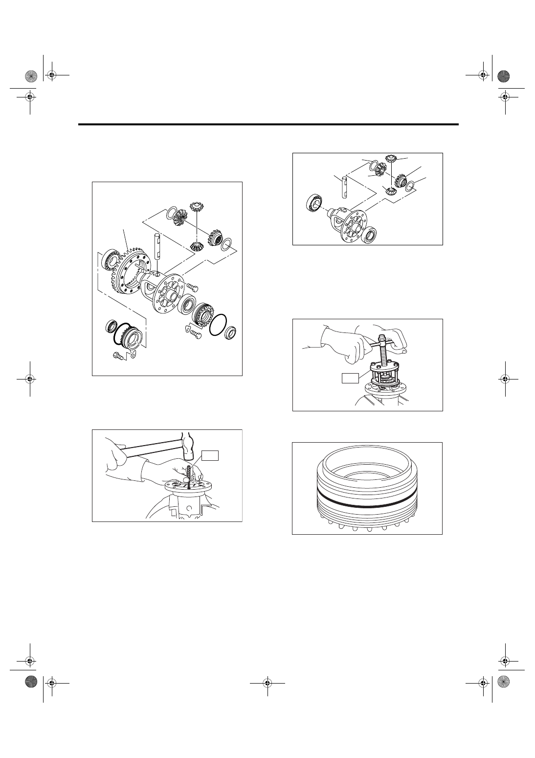
C: DISASSEMBLY
1. DIFFERENTIAL CASE ASSEMBLY
1) Loosen the twelve bolts and remove hypoid driv-
en gear.
2) Drive out the straight pin from differential assem-
bly toward hypoid driven gear side.
ST
899904100
REMOVER
3) Pull out the pinion shaft, and remove the differ-
ential bevel pinion, bevel gear and washer.
4) Using the ST, remove the roller bearing.
ST
899524100
PULLER SET
2. SIDE RETAINER
1) Remove the O-ring.
(A) Hypoid driven gear
(A)
MT-00275
MT-00276
ST
(A) Pinion shaft
(B) Bevel pinion
(C) Bevel gear
(D) Washer
MT-00277
(A)
(D)
(D)
(C)
(C)
(B)
(B)
MT-00278
ST
MT-00279
5MT-86
MANUAL TRANSMISSION AND DIFFERENTIAL
Front Differential Assembly
2) Remove the oil seal.
NOTE:
Do not reuse the oil seal. Replace with a new oil
seal.
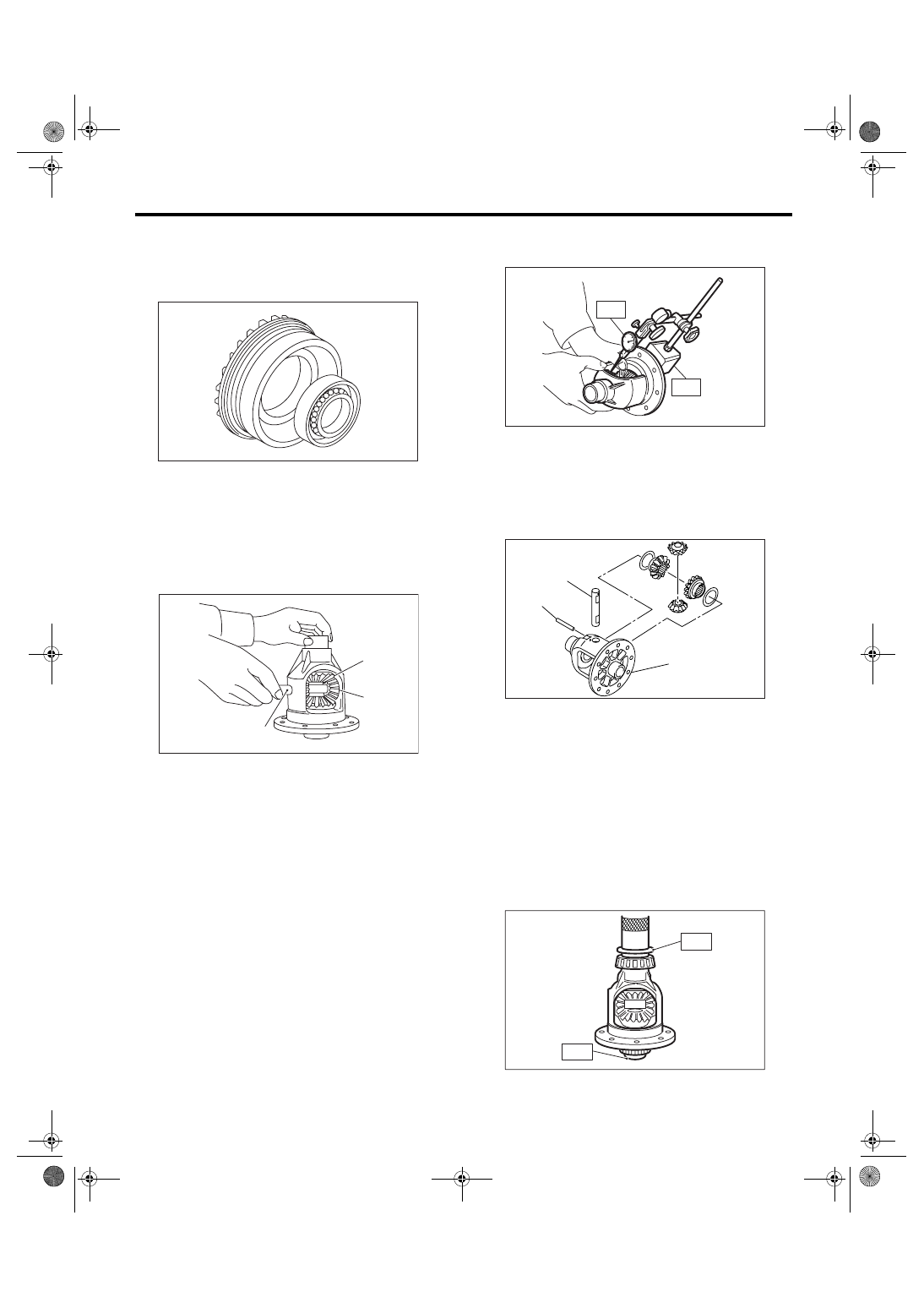
D: ASSEMBLY
1. DIFFERENTIAL CASE ASSEMBLY
1) Install the bevel gear and bevel pinion together
with washers, and insert the pinion shaft.
NOTE:
Face the chamfered side of washer toward gear.
2) Measure the backlash between bevel gear and
pinion. If it is not within specifications, install a suit-
able washer to adjust. <Ref. to 5MT-88, ADJUST-
MENT, Front Differential Assembly.>
NOTE:
Be sure the pinion gear teeth contacts adjacent
gear teeth during measurement.
ST1
498247001
MAGNET BASE
ST2
498247100
DIAL GAUGE
Standard backlash:
0.13 — 0.18 mm (0.0051 — 0.0071 in)
3) Align the pinion shaft and differential case at
their holes, and drive the straight pin into holes
from the hypoid driven gear side, using ST.
NOTE:
Lock the straight pin after installing.
ST
899904100
REMOVER
4) Install the roller bearing to differential case.
NOTE:
• Do not apply pressure in excess of 10 kN (1 ton,
1.1 US ton, 1.0 Imp ton).
• Be careful because the roller bearing outer races
are used as a set.
ST1
499277100
BUSHING 1-2 INSTALLER
ST2
398497701
ADAPTER
(A) Bevel pinion
(B) Bevel gear
(C) Pinion shaft
MT-00363
MT-00284
(A)
(B)
(C)
(A) Pinion shaft
(B) Differential case
(C) Straight pin
MT-00285
ST1
ST2
MT-00286
(A)
(C)
(B)
MT-00287
ST1
ST2
Нет комментариевНе стесняйтесь поделиться с нами вашим ценным мнением.
Текст