Subaru Legacy (2005 year). Service manual — part 657
5MT-75
MANUAL TRANSMISSION AND DIFFERENTIAL
Input Shaft Assembly
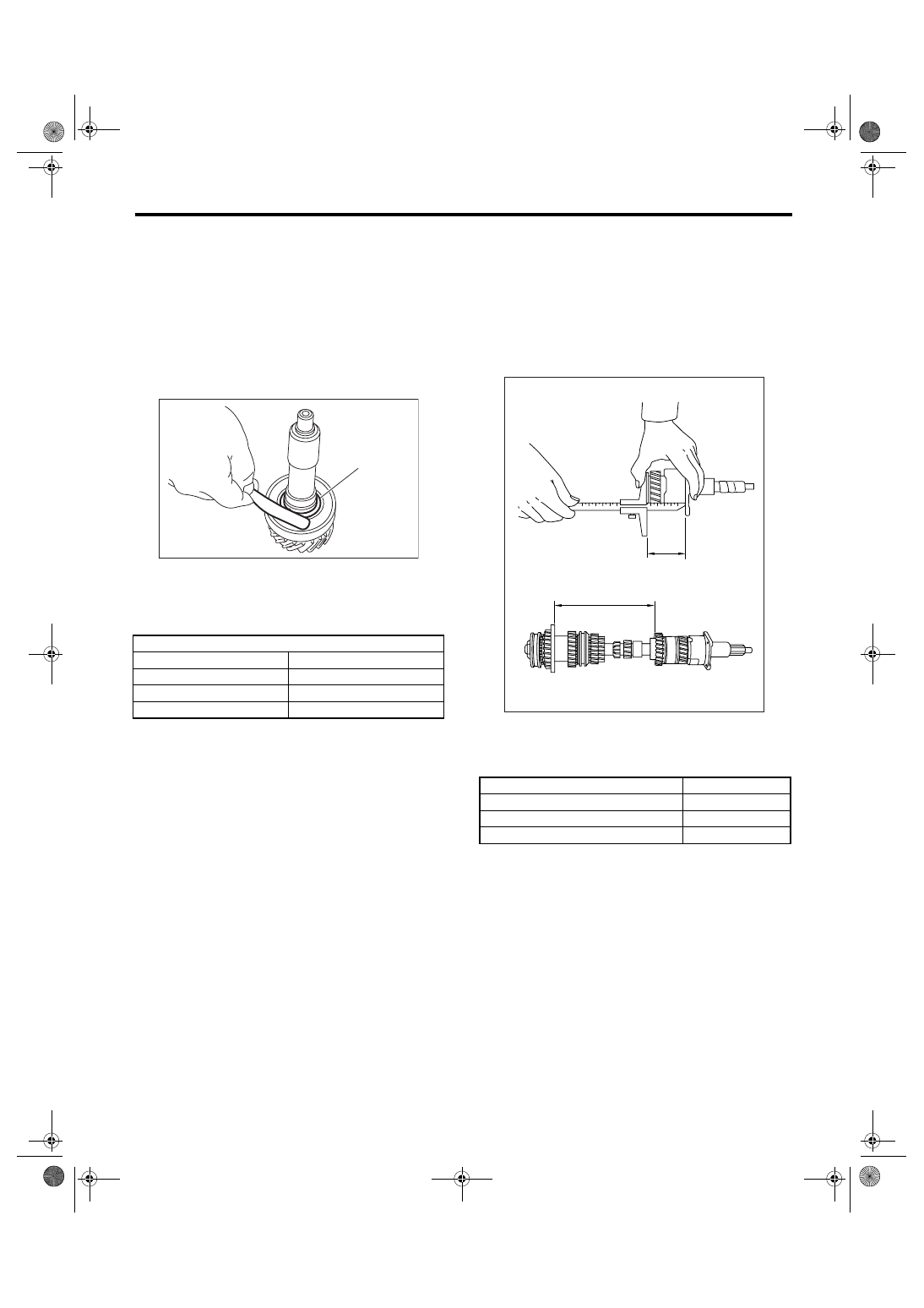
7) O-ring
Replace the O-ring if the sealing face is deformed,
hardened, damaged, worn or defective in any way.
8) Gearshift mechanism
Repair or replace the gearshift mechanism if ex-
cessively worn, bent or defective in any way.
9) Measure the clearance between snap ring and
ball bearing using thickness gauge.
Clearance:
0 — 0.12 mm (0 — 0.0047 in)
If the measurement is not within specification, se-
lect a suitable snap ring.
F: ADJUSTMENT
1) Place transmission main shaft assembly and in-
put shaft on transmission main case without shim.
2) The proper number of shim can be determined
as follows:
D = A
− (B + C)
A: Main case length (353 mm (13.90 in))
B: Input shaft complete length
C: Main shaft assembly length
NOTE:
The thickness of shim is 0.45 to 0.55 mm (0.0177 to
0.0217 in).
(A) Snap ring
Snap ring
Part No.
Thickness mm (in)
805028050
2.48 (0.0976)
805028060
2.56 (0.1008)
805028070
2.64 (0.1039)
MT-00239
(A)
Dimension “D” mm (in)
Number of shims
52.50 — 53.11 (2.0669 — 2.0909)
—
52.00 — 52.49 (2.0472 — 2.0665)
1
51.26 — 51.99 (2.0181 — 2.0468)
2
MT-01015
C
B
5MT-76
MANUAL TRANSMISSION AND DIFFERENTIAL
Drive Pinion Shaft Assembly
18.Drive Pinion Shaft Assembly
A: REMOVAL
1) Remove the manual transmission assembly
from vehicle. <Ref. to 5MT-30, REMOVAL, Manual
Transmission Assembly.>
2) Remove the transfer case with extension case
assembly. <Ref. to 5MT-43, REMOVAL, Transfer
Case and Extension Case Assembly.>
3) Remove the transmission case. <Ref. to 5MT-
55, REMOVAL, Transmission Case.>
4) Remove the drive pinion shaft assembly.
NOTE:
Use a hammer handle, etc. to remove if too tight.
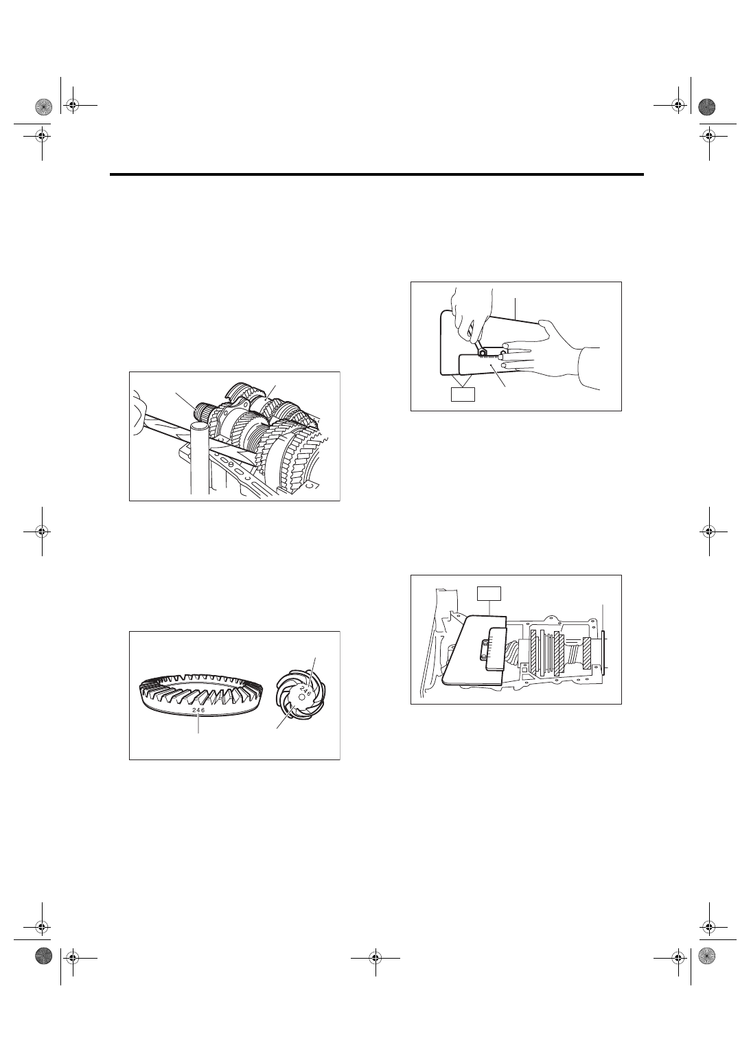
B: INSTALLATION
1) Remove the differential assembly.
2) Use hypoid driven gear of its match number cor-
responding with upper one on the drive pinion (A).
The figure (B) shows a number for shim adjust-
ment. If no number is shown, the value is zero.
3) Place the drive pinion shaft assembly on the
transmission main case RH without shim and tight-
en the bearing mounting bolts.
4) Inspect and adjust the ST.
NOTE:
• Loosen the two bolts and adjust so that the scale
indicates 0.5 correctly when the plate end and the
scale end are on the same level.
• Tighten the two bolts.
ST
499917500
DRIVE PINION GAUGE
ASSY
5) Position the ST by inserting the knock pin of ST
into the knock hole in the transmission case.
ST
499917500
DRIVE PINION GAUGE
ASSY
6) Slide the drive pinion gauge scale with finger tip
and read the value at the point where it matches
with the end face of drive pinion.
ST
499917500
DRIVE PINION GAUGE
ASSY
7) The thickness of shim shall be determined by
adding the value indicated on drive pinion to the
value indicated on the ST. (Add if the number on
drive pinion is prefixed by +, and subtract if the
number is prefixed by
−.)
ST
499917500
DRIVE PINION GAUGE
ASSY
8) Select one to three shims in the next table for the
value determined as described above, and take the
shim(s) which thickness is closest to the said value.
(A) Main shaft ASSY
(B) Drive pinion shaft ASSY
(A) Match number
(B) Number for shim adjustment
MT-00161
( A )
( B )
MT-00990
(A)
(B)
(A)
+0.1
(A) Plate
(B) Scale
(A) Adjust clearance to zero without shim.
MT-00242
(A)
(B)
ST
MT-00243
(A)
ST
5MT-77
MANUAL TRANSMISSION AND DIFFERENTIAL
Drive Pinion Shaft Assembly
9) Install the differential assembly. <Ref. to 5MT-
84, INSTALLATION, Front Differential Assembly.>
10) Set the transmission main shaft assembly and
drive pinion assembly in position. (So there is no
clearance between these two when moved all the
way to the front). Inspect the suitable 1st — 2nd,
3rd — 4th and 5th shifter fork so that the coupling
sleeve and reverse driven gear are positioned in
the center of their synchronizing mechanisms.
<Ref. to 5MT-81, INSPECTION, Drive Pinion Shaft
Assembly.>
11) Install the transmission case. <Ref. to 5MT-57,
INSTALLATION, Transmission Case.>
12) Install the transfer case with extension case as-
sembly. <Ref. to 5MT-43, INSTALLATION, Trans-
fer Case and Extension Case Assembly.>
13) Install the manual transmission assembly to ve-
hicle. <Ref. to 5MT-30, Manual Transmission As-
sembly.>
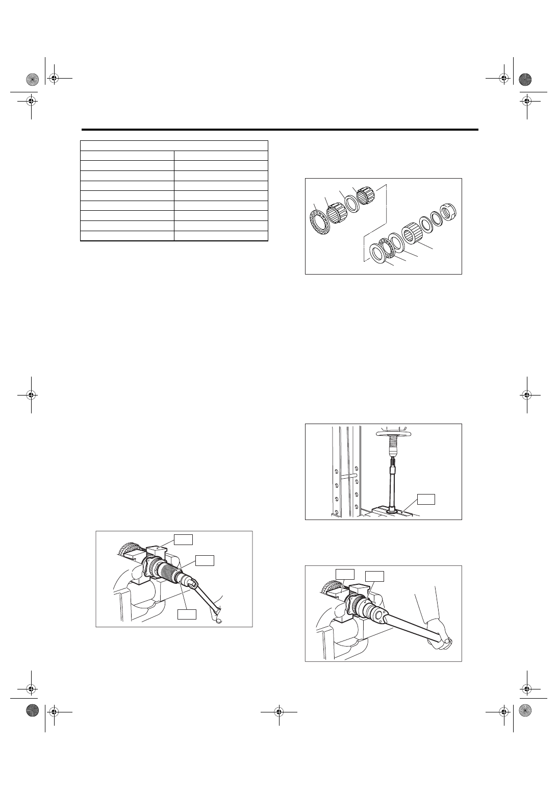
C: DISASSEMBLY
NOTE:
Attach a cloth to the end of driven shaft (on the fric-
tional side of thrust needle bearing) to prevent
damage during disassembly or reassembly.
1) Unlock the caulking of lock nut. Remove the lock
nut using ST1, ST2 and ST3.
ST1
899884100
HOLDER
ST2
498427100
STOPPER
ST3
899988608
SOCKET WRENCH (27)
2) Draw out the drive pinion from driven shaft.
Remove the differential bevel gear sleeve, adjust-
ing washer No. 1, adjusting washer No. 2, thrust
bearing, needle bearing and drive pinion collar.
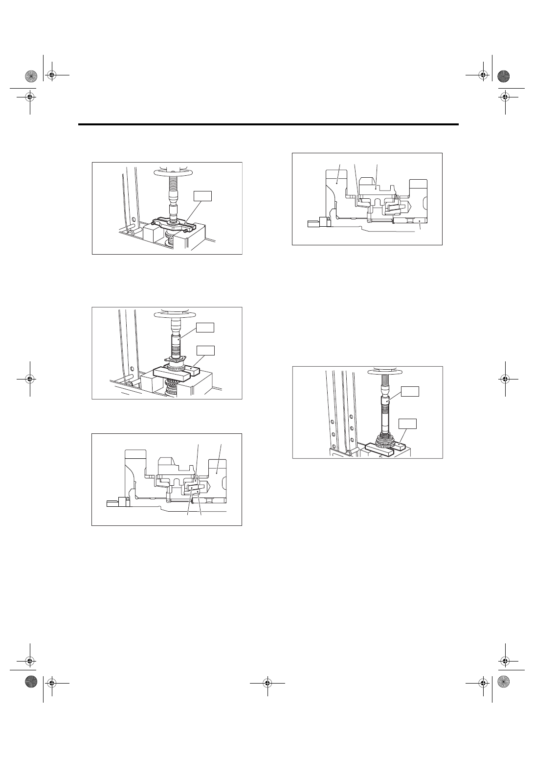
3) Remove the roller bearing and washer using ST
and press.
NOTE:
Do not reuse the roller bearing.
ST
498077000
REMOVER
4) Unlock the caulking of lock nut. Remove the lock
nut using ST1 and ST2.
ST1
499987300
SOCKET WRENCH (50)
ST2
899884100
HOLDER
Drive pinion shim
Part Number
Thickness mm (in)
32295AA031
0.150 (0.0059)
32295AA041
0.175 (0.0069)
32295AA051
0.200 (0.0079)
32295AA061
0.225 (0.0089)
32295AA071
0.250 (0.0098)
32295AA081
0.275 (0.0108)
32295AA091
0.300 (0.0118)
32295AA101
0.500 (0.0197)
ST1
ST2
MT-00244
ST3
(A) Differential bevel gear sleeve
(B) Washer No. 1 (25
× 37.5 × t)
(C) Thrust bearing (25
× 37.5 × 3)
(D) Washer No. 2 (25
× 37.5 × 4)
(E) Needle bearing (25
× 30 × 20)
(F) Drive pinion collar
(G) Needle bearing (30
× 37 × 23)
(H) Thrust bearing (33
× 50 × 3)
MT-00245
( B )
( D )
( C )
( A )
( F )
( H )
( G )
( E )
MT-00246
ST
MT-00247
ST1
ST2
5MT-78
MANUAL TRANSMISSION AND DIFFERENTIAL
Drive Pinion Shaft Assembly
5) Remove the 5th driven gear using ST.
ST
499857000
5TH DRIVEN GEAR REMOV-
ER
6) Remove the woodruff key.
7) Remove the roller bearing and 3rd-4th driven
gear using ST1 and ST2.
ST1
499757002
INSTALLER
ST2
899714110
REMOVER
8) Remove the key.
9) Remove the 2nd driven gear, inner baulk ring,
synchro cone and outer baulk ring.
10) Remove the 1st driven gear, 2nd gear bushing,
gear and hub using ST1 and ST2.
NOTE:
Replace the gear and hub if necessary. Do not dis-
assemble because they must engage at a specified
point. If they have to be disassembled, mark the
engaging point on the spline beforehand.
ST1
499757002
INSTALLER
ST2
899714110
REMOVER
D: ASSEMBLY
1) Install the sleeve and hub assembly by matching
alignment marks.
(A) 2nd driven gear
(B) Inner baulk ring
(C) Synchro cone
(D) Outer baulk ring
MT-00248
S T
MT-00249
ST1
ST2
MT-00997
(A)
(B)
(D)
(C)
(A) 1st driven gear
(B) Inner baulk ring
(C) Hub
(D) 2nd gear bushing
MT-00991
(A)
(D)
(C)
(B)
MT-00251
ST1
ST2
Нет комментариевНе стесняйтесь поделиться с нами вашим ценным мнением.
Текст