Subaru Legacy (2005 year). Service manual — part 709
FS-7
FRONT SUSPENSION
Wheel Alignment
2. Wheel Alignment
A: INSPECTION
Check the following items before taking wheel alignment measurement.
Check items before taking wheel alignment measurement:
• Tire inflation pressure
• Unbalanced right and left tire wear, size difference
• Tire runout
• Excessive play and wear in ball joint
• Excessive play and wear in tie rod end
• Excessive play in wheel bearing
• Right and left wheel base imbalance
• Deformation and excessive play in steering link
• Deformation and excessive play in suspension parts
Check, adjust and measure the wheel alignment in accordance with the procedures indicated in the figure.
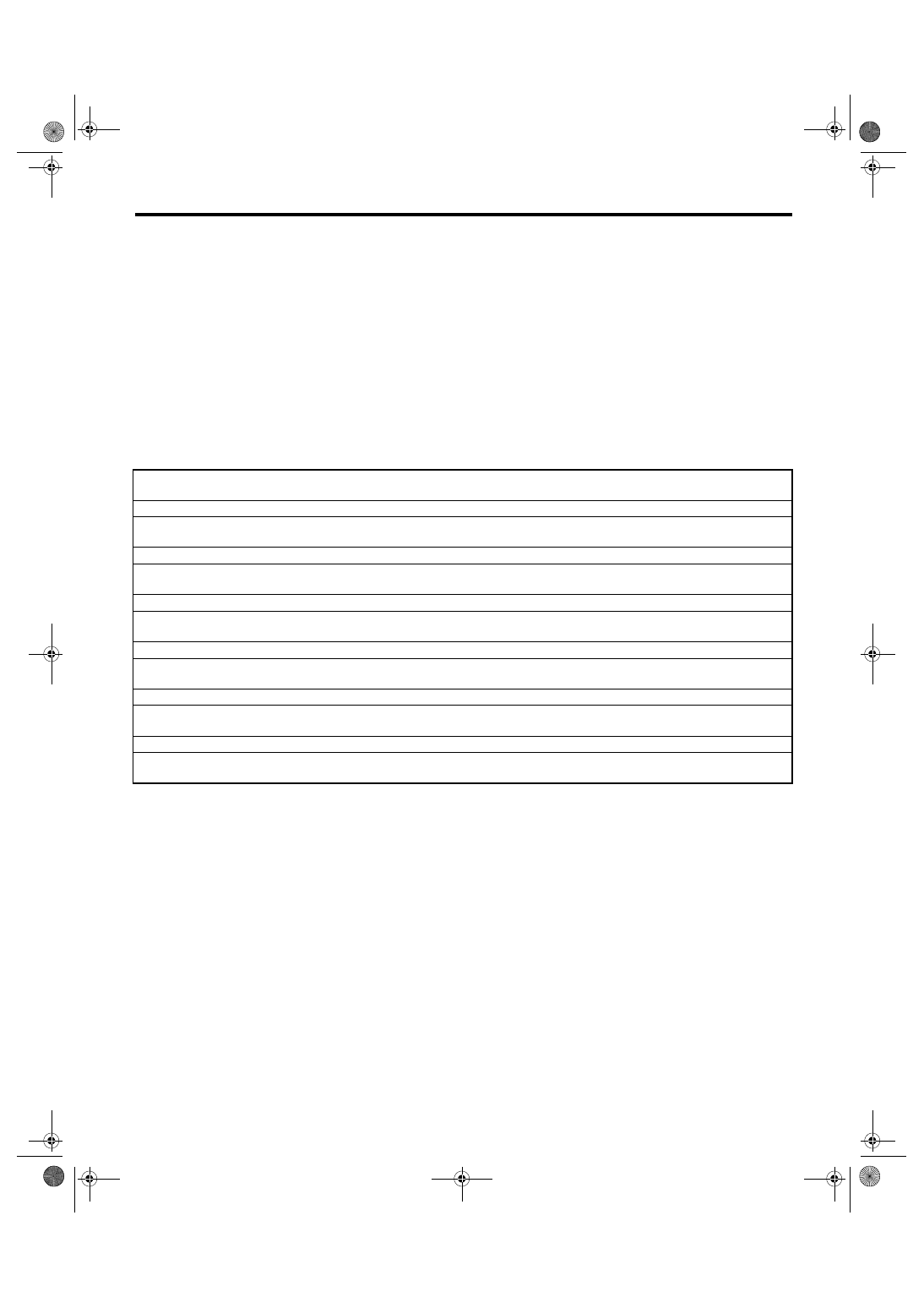
1. WHEEL ARCH HEIGHT
1) Park the vehicle on a level surface.
2) Set the vehicle under “curb weight” condition.
(Make the luggage compartment empty, install the
spare tire, jack and service tools, and top up the
fuel tank.)
3) Set the steering wheel in a straight-ahead posi-
tion, and stabilize the suspensions by moving the
vehicle straight more than 5 m (16 ft).
4) Suspend a thread from wheel arch (point “A” in
the figure below) to determine the point directly
above the center of wheel.
5) Measure the distance between the point “A” and
the center of wheel.
Wheel arch height (front and rear wheels)
<Ref. to FS-7, WHEEL ARCH HEIGHT, INSPECTION, Wheel Alignment.>
↓
Camber (front and rear wheels)
<Ref. to FS-9, CAMBER, INSPECTION, Wheel Alignment.>
↓
Caster (front wheel)
<Ref. to FS-10, CASTER, INSPECTION, Wheel Alignment.>
↓
Steering angle
<Ref. to FS-11, STEERING ANGLE, INSPECTION, Wheel Alignment.>
↓
Front wheel toe-in
<Ref. to FS-11, FRONT WHEEL TOE-IN, INSPECTION, Wheel Alignment.>
↓
Rear wheel toe-in
<Ref. to FS-12, REAR WHEEL TOE-IN, INSPECTION, Wheel Alignment.>
↓
Thrust angle
FS-8
FRONT SUSPENSION
Wheel Alignment
(1)
Wheel arch height
(4)
Front wheel arch height
(7)
Point of measurement
(2)
Front fender
(5)
Rear wheel arch height
(8)
Tip end of spindle
(3)
Rear quarter
(6)
Flange bend line
Wheel arch height specification mm (in) (Tolerance
±12 mm)
Model
Sedan
Wagon
2.0 i
2.5 i
2.0 GT
3.0 R, 3.0 R
spec. B
2.0 i, 2.5 i
2.0 GT, 3.0
R
3.0 R spec.
B
OUTBACK
2.5 i, OUT-
BACK 3.0 R
Front
376 (14.8)
372 (14.6)
381 (15.0)
376 (14.8)
372 (14.6)
429 (16.9)
Rear
360 (14.2)
375 (14.8)
365 (14.4)
430 (16.9)
FS-00125
A
A
A
(4)
(1)
(2)
(3)
(1)
(5)
(1)
(7)
(6)
(8)
FS-9
FRONT SUSPENSION
Wheel Alignment
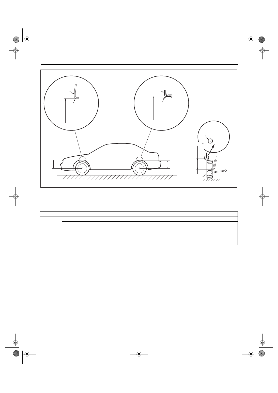
2. CAMBER
• INSPECTION
1) Place the front wheel on turning radius gauge.
Make sure the ground contacting surfaces of front
and rear wheels are set at the same height.
2) Set the ST into the center of wheel, and then set
the wheel alignment gauge.
ST
927380002
ADAPTER
3) Measure the camber angle in accordance with
the operation manual for wheel alignment gauge.
• FRONT CAMBER ADJUSTMENT
1) When adjusting the camber, adjust it to the fol-
lowing value.
2) Loosen the two self-locking nuts located at the
lower front portion of strut.
NOTE:
When the adjusting bolt needs to be loosened or
tightened, hold its head with a wrench and turn the
self-locking nut.
3) Turn the camber adjusting bolt so that the cam-
ber is set at specification.
NOTE:
Moving the adjusting bolt by one scale changes the
camber by approx. 0
°15′.
(1) Alignment gauge
(2) Turning radius gauge
Model
Camber (Differences between
RH and LH 45
′ or less)
Sedan
Except for 3.0 R
spec. B
−0°20′±0°45′
3.0 R spec. B
−0°25′±0°45′
Wagon
2.0 i, 2.5 i
−0°15′±0°45′
2.0 GT, 3.0 R
−0°20′±0°45′
3.0 R spec. B
−0°25′±0°45′
OUTBACK 2.5 i,
OUTBACK 3.0 R
0
°30′±0°45′
Model
Camber (Differences between
RH and LH: 45
′ or less)
Sedan
Except for 3.0 R
spec. B
−0°20′±0°30′
3.0 R spec. B
−0°25′±0°30′
Wagon
2.0 i, 2.5 i
−0°15′±0°30′
2.0 GT, 3.0 R
−0°20′±0°30′
3.0 R spec. B
−0°25′±0°30′
OUTBACK 2.5 i,
OUTBACK 3.0 R
0
°30′±0°30′
FS-00007
(1)
(2)
ST
(1) Strut
(2) Adjusting bolt
(3) Housing
(4) Outer
(5) Inner
(6) Camber is increased
(7) Camber is decreased
(1)
(4)
(6)
(7)
(2)
(3)
FS-00008
(5)
FS-10
FRONT SUSPENSION
Wheel Alignment
4) Tighten two new self-locking nuts.
Tightening torque:
175 N
⋅
m (17.8 kgf-m, 129 ft-lb)
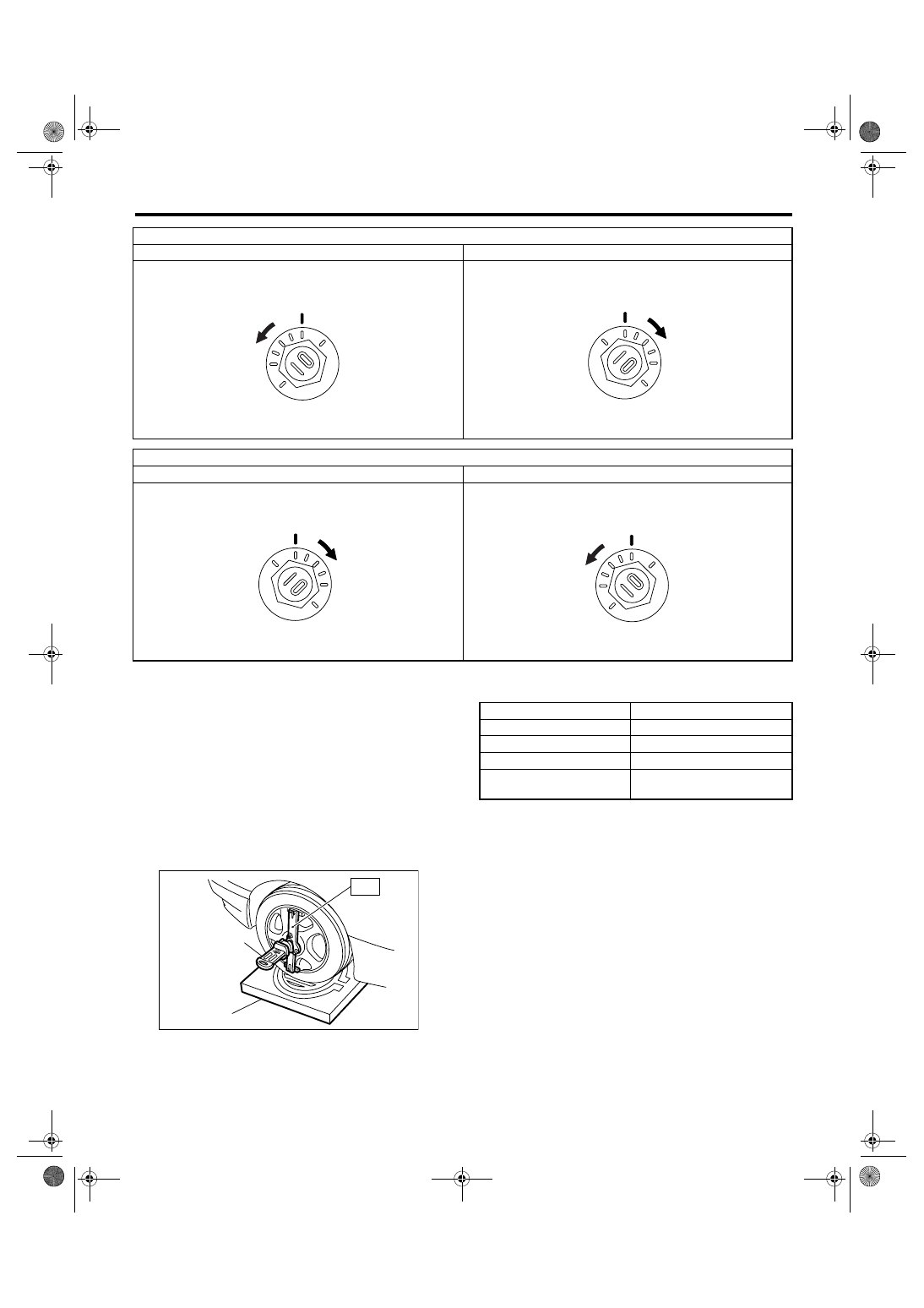
3. CASTER
• INSPECTION
1) Place the front wheel on turning radius gauge.
Make sure the ground contacting surfaces of front
and rear wheels are set at the same height.
2) Set the ST into the center of wheel, and then set
the wheel alignment gauge.
ST
927380002
ADAPTER
3) Measure the caster angle in accordance with the
operation manual for wheel alignment gauge.
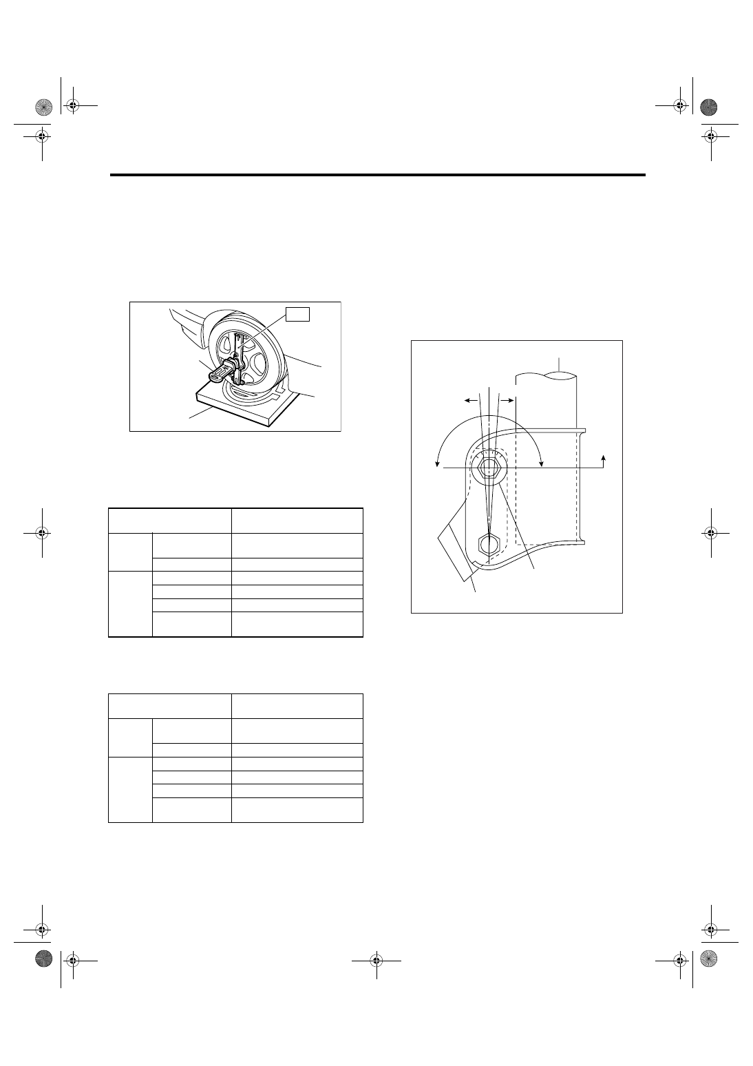
To increase camber.
Rotate the left side counterclockwise.
Rotate the right side clockwise.
To decrease camber.
Rotate the left side clockwise.
Rotate the right side counterclockwise.
FS-00009
FS-00010
FS-00010
FS-00009
(1) Alignment gauge
(2) Turning radius gauge
FS-00007
(1)
(2)
ST
Model
Caster
Sedan
6
°00′
Wagon
5
°45′
OUTBACK
5
°05′
3.0 R spec. B (sedan &
wagon)
6
°05′
Нет комментариевНе стесняйтесь поделиться с нами вашим ценным мнением.
Текст