Subaru Legacy IV (2008 year). Service manual — part 925
VDC(diag)-15
Subaru Select Monitor
VEHICLE DYNAMICS CONTROL (VDC) (DIAGNOSTICS)
2. READ CURRENT DATA
1) On the «Main Menu» display, select the {Each System Check}.
2) On the «System Selection Menu» display, select the {Brake Control System}.
3) Click the [OK] button after the {VDC} is displayed.
4) On the «Brake Control Diagnosis» display, select the {Current Data Display & Save}.
5) On the «Data Display Menu» display, select the data display method.
6) Using the scroll key, scroll the display screen up or down until necessary data is shown.
• A list of the support data is shown in the following table.
NOTE:
For detailed operation procedure, refer to the “PC application help for Subaru Select Monitor”.
3. FUNCTION CHECK
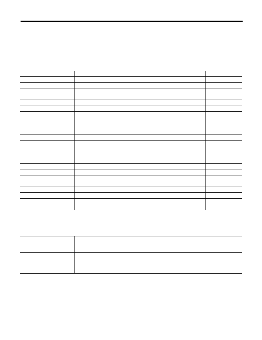
Display
Contents to be displayed
Unit of measure
FR Wheel Speed
Wheel speed detected by front ABS wheel speed sensor RH is displayed.
km/h or MPH
FL Wheel Speed
Wheel speed detected by front ABS wheel speed sensor LH is displayed.
km/h or MPH
RR Wheel Speed
Wheel speed detected by rear ABS wheel speed sensor RH is displayed.
km/h or MPH
RL Wheel Speed
Wheel speed detected by rear ABS wheel speed sensor LH is displayed.
km/h or MPH
Steering Angle Sensor Op
Steering angle detected by steering angle sensor is displayed.
deg
Yaw Rate Sensor Output
Vehicle angular speed detected by yaw rate sensor is displayed.
deg/s
Pressure Sensor Output
Brake fluid pressure detected by pressure sensor is displayed.
bar
Lateral G Sensor output
Vehicle lateral acceleration detected by lateral G sensor is displayed.
m/s (m/s
2
)
ABS_CM Power Voltage
Voltage supplied to VDCCM&H/U is displayed.
V
E/G Control Stop Flag
Engine control command signal is displayed.
1 or 0
ABS Control Flag
ABS operation condition is displayed.
ON or OFF
EBD Control Flag
EBD operation condition is displayed.
ON or OFF
TCS Control Flag
TCS operation condition is displayed.
ON or OFF
VDC Control Flag
VDC operation condition is displayed.
ON or OFF
OFF Lamp
ON/OFF condition of VDC OFF indicator light is displayed.
ON or OFF
EBD Warning Light
ON operation of the EBD warning light is displayed.
ON or OFF
ABS Warning Light
ON operation of the ABS warning light is displayed.
ON or OFF
VDC Warning Light
ON operation of the VDC warning light is displayed.
ON or OFF
Valve Relay Signal
Valve relay operation signal is displayed.
ON or OFF
Motor Relay Signal
Motor relay operation signal is displayed.
ON or OFF
M. Relay monitor Voltage
Voltage applied to the motor relay is displayed.
V
OFF SW Signal
Operation condition of VDC OFF switch is displayed.
ON or OFF
Brake Switch
Brake ON/OFF is displayed.
ON or OFF
Display
Contents of display
Index No.
ABS Sequence Control Mode
Operate the valve and pump motor continuously
to perform the ABS sequence control.
<Ref. to ABS-10, ABS Sequence Control.>
VDC Check Mode
Operate the valve and pump motor continuously
to perform the VDC sequence control.
<Ref. to VDC-13, VDC Sequence Control.>
Set mode Str.
A.Sen.N&Lat.GSen.0p
Set the steering angle sensor neutral position
and the lateral G sensor “0” point.
<Ref. to VDC-18, Steering Angle Sensor.>

VDC(diag)-16
Subaru Select Monitor
VEHICLE DYNAMICS CONTROL (VDC) (DIAGNOSTICS)
4. FREEZE FRAME DATA
NOTE:
• Data stored at the time of trouble occurrence is
shown on display.
• Each time a trouble occurs, the latest information
is stored in the freeze frame data in memory.
• If a freeze frame data is not properly stored in
memory (due to a drop in VDCCM power supply,
etc.), a DTC suffixed with a question mark “?” will
appear on the Subaru Select Monitor display. This
shows it may be an unreliable reading.
5. PARAMETER SELECTION
CAUTION:
• Subaru Select Monitor is required for param-
eter selection.
• This function can be used for the replace-
ment VDCCM&H/U and VDCCM.
NOTE:
• When a VDCCM is replaced with a replacement,
use this function to select and register parameters
to the VDCCM.
• For confirmation of applied models, refer to the
“Model number plate” attached to the vehicles.
<Ref. to ID-2, IDENTIFICATION, Identification.>
• If a wrong applied model is written, it can be re-
written.
• When no data is registered, ABS/EBD/VDC
warning light illuminates and the DTC “Parameter
selection error” is detected.
1) Connect the Subaru Select Monitor.
2) On the «Main Menu» display, select the {Each
System Check}.
3) On the «System Selection Menu» display, select
the {Brake Control System}.
4) Click the [OK] button after the {VDC} is dis-
played.
5) On the «Brake Control Diagnosis» display, se-
lect the {Selection of Parameter}.
6) Check the applied model indicated in the “Model
number plate”. <Ref. to ID-2, IDENTIFICATION,
Identification.>
7) Enter the applied model of 7-digit alphanumeric
characters and press the [Enter] key.
8) When the confirmation screen indicating the ve-
hicle information appears, check that the correct
applied model and grade are displayed and click
the [OK] button.
NOTE:
When the displayed applied model and grade are
different from those of the vehicle, perform registra-
tion operations again after clicking the [OK] button.
9) Execute Clear Memory after parameter selec-
tion and registration operations because the DTC
for “Parameter selection error” is memorized.
Display
Contents to be displayed
Steering Angle
Sensor Op
Steering angle detected by steering
angle sensor is displayed.
Yaw Rate Sensor
Output
Vehicle angular speed detected by yaw
rate sensor is displayed.
Lateral G Sensor
output
Vehicle lateral acceleration detected by
lateral G sensor is displayed.
Pressure Sensor
Output
Brake fluid pressure detected by pres-
sure sensor is displayed.
Vehicle Speed
Vehicle speed calculated by VDC con-
trol module is displayed.
FR Wheel Speed
Wheel speed detected by front ABS
wheel speed sensor RH is displayed in
km/h or MPH.
FL Wheel Speed
Wheel speed detected by front ABS
wheel speed sensor LH is displayed in
km/h or MPH.
RR Wheel Speed
Wheel speed detected by rear ABS
wheel speed sensor RH is displayed in
km/h or MPH.
RL Wheel Speed
Wheel speed detected by rear ABS
wheel speed sensor LH is displayed in
km/h or MPH.
Accel. Opening
Angle
Acceleration opening is displayed.
Engine Speed
Engine speed on malfunction occur-
rence is displayed.
Gear Position
Gear position on malfunction occur-
rence is displayed.
ABS_CM Power
Voltage
Voltage supplied to VDC control module
is displayed.
Steering angle
flag
Whether the absolute angle of the
steering angle sensor was determined
is displayed.
E/G Control Stop
Flag
Engine control command signal is dis-
played.
VDC Control Flag
VDC control condition is displayed.
EBD Control Flag
EBD control condition is displayed.
TCS Control Flag
TCS control condition is displayed.
ABS Control Flag
ABS control condition is displayed.
OFF Switch
Detection
ON/OFF condition of the VDC operated
by the driver is displayed.
Brake Switch
Brake ON/OFF is displayed.
VDC(diag)-17
Subaru Select Monitor
VEHICLE DYNAMICS CONTROL (VDC) (DIAGNOSTICS)
6. PARAMETER CHECK
NOTE:
The parameter data registered in the VDCCM is
shown on the display.
1) Connect the Subaru Select Monitor.
2) On the «Main Menu» display, select the {Each
System Check}.
3) On the «System Selection Menu» display, select
the {Brake Control System}.
4) Click the [OK] button after the {VDC} is dis-
played.
5) On the «Brake Control Diagnosis» display, se-
lect the {Confirm on parameter}.
6) On the {Confirm on parameter} display screen,
check that the applied model and grade of the tar-
get vehicle are included, and click the [OK] button.
7) If the applied model and grade of the target ve-
hicle are not included on the {Confirm on parame-
ter} display screen, perform parameter selection
and registration. <Ref. to VDC(diag)-16, PARAME-
TER SELECTION, OPERATION, Subaru Select
Monitor.>
VDC(diag)-18
Subaru Select Monitor
VEHICLE DYNAMICS CONTROL (VDC) (DIAGNOSTICS)
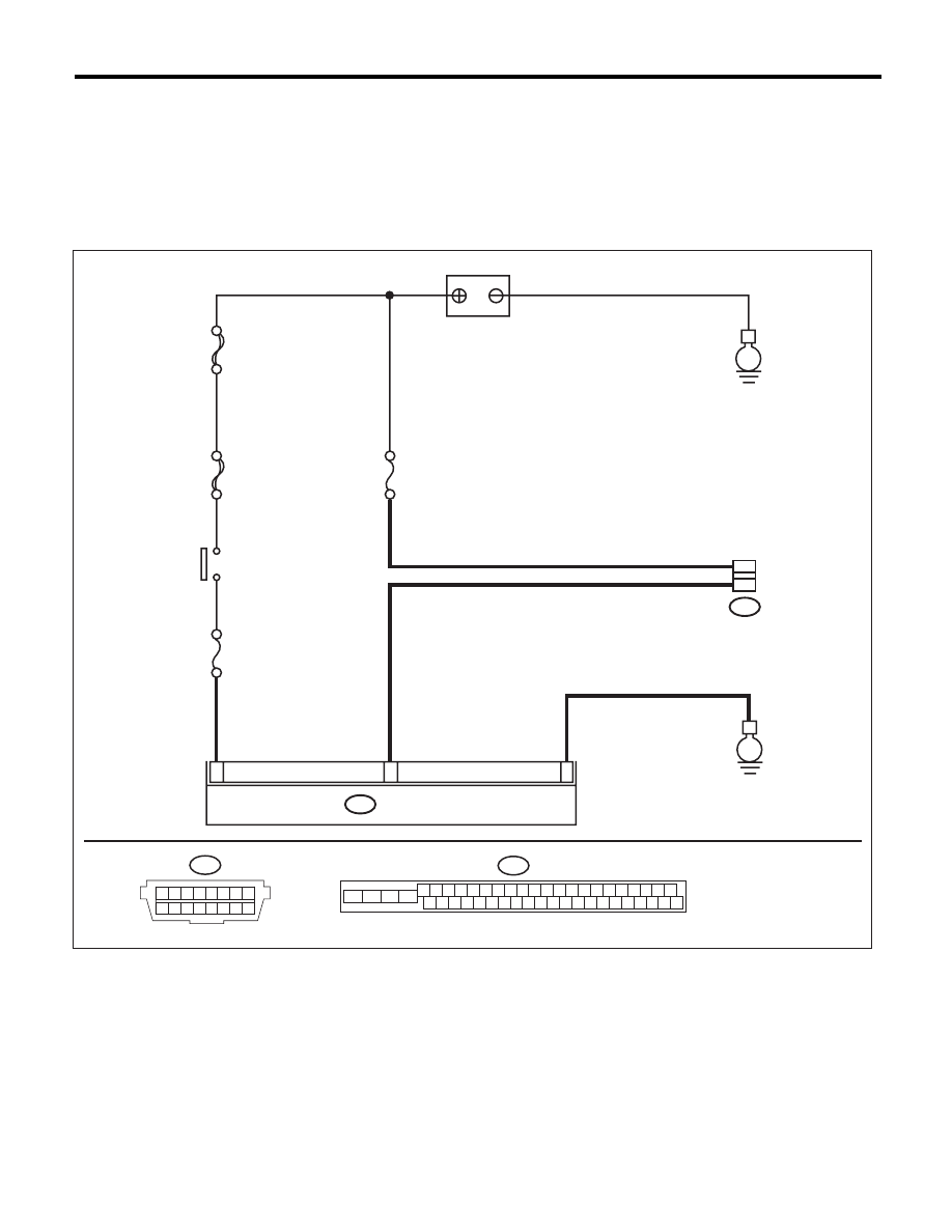
B: INSPECTION
1. COMMUNICATION FOR INITIALIZING IMPOSSIBLE
DETECTING CONDITION:
Defective harness connector
TROUBLE SYMPTOM:
Communication is impossible between VDC and Subaru Select Monitor.
WIRING DIAGRAM:
7
28
MAIN SBF
SBF-6
F/B
No.33
M/B
No.13
B310
VDCCM & H/U
E
25
B40
7
16
E
B310
4 5 6 7 8 9
26 27 28 29 30
2 3
1
31 32 33 34 35 36
10 11
14 15 16 17 18 19
37 38 39 40
12 13
41 42 43 44 45 46
20 21
23
24
22
25
VDC00498
B40
1 2 3 4 5 6 7 8
9 10 11 12 13 14 15 16
BATTERY
IGNITION
SWITCH
DATA LINK
CONNECTOR
Нет комментариевНе стесняйтесь поделиться с нами вашим ценным мнением.
Текст