Subaru Legacy IV (2008 year). Service manual — part 924
VDC(diag)-11
Control Module I/O Signal
VEHICLE DYNAMICS CONTROL (VDC) (DIAGNOSTICS)
5. Control Module I/O Signal
A: ELECTRICAL SPECIFICATION
NOTE:
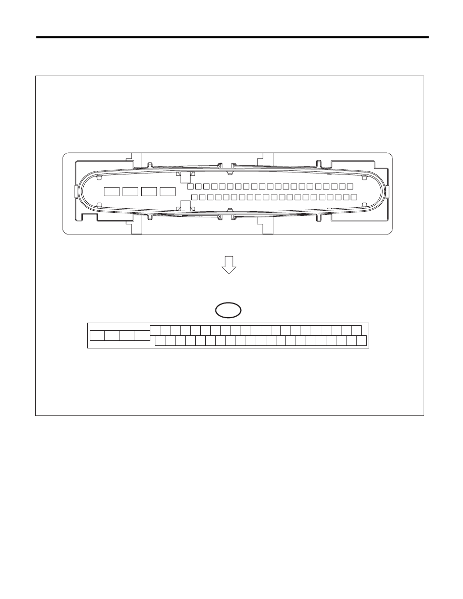
• Terminal numbers in VDCCM&H/U connector are shown in the figure.
• When the connector is removed from VDCCM&H/U, the ABS warning light, VDC warning light and VDC
OFF indicator light illuminate.
VDC00457
B310
4 5 6 7 8 9
26 27 28 29 30
2 3
1
31 32 33 34 35 36
10 11
14 15 16 17 18 19
37 38 39 40
12 13
41 42 43 44 45 46
20 21
23
24
22
25
VDC(diag)-12
Control Module I/O Signal
VEHICLE DYNAMICS CONTROL (VDC) (DIAGNOSTICS)
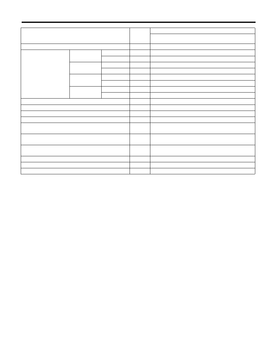
Content
Terminal
No.
(+) — (–)
Input/Output signal
Measured value and measuring conditions
Power supply
28 — 25
10 — 15 V when the ignition switch is ON.
ABS wheel speed sensor
Front LH wheel
Power supply
26 — 25
4.5 — 16.5 V
Signal
1
5.9 — 16.8 mA: Rectangle waveform
Front RH wheel
Power supply
5 — 25
4.5 — 16.5 V
Signal
6
5.9 — 16.8 mA: Rectangle waveform
Rear LH wheel
Power supply
2 — 25
4.5 — 16.5 V
Signal
27
5.9 — 16.8 mA: Rectangle waveform
Rear RH wheel
Power supply
3 — 25
4.5 — 16.5 V
Signal
4
5.9 — 16.8 mA: Rectangle waveform
CAN communication line (+)
35
2.5 — 1.5 V pulse signal
CAN communication line (–)
10
3.5 — 2.5 V pulse signal
Valve relay power supply
24 — 25
10 — 15 V when the ignition switch is ON.
Motor relay power supply
23 — 22
10 — 15 V when the ignition switch is ON.
ABS warning light
32 — 25
After turning the ignition switch to ON, 10 — 15 V during
1.5 seconds, and 1.5 V or less after 1.5 seconds passed.
Brake warning light (EBD warning light)
8 — 25
After turning the ignition switch to ON, 10 — 15 V during
1.5 seconds, and 1.5 V or less after 1.5 seconds passed.
Stop light switch
30 — 25
1.5 V or less when the stop light is OFF; otherwise,
10 — 15 V when the stop light is ON.
Subaru Select Monitor
7 — 25
0
mo 12 V pulse (in communication)
Vehicle speed output signal
33
0
mo 12 V pulse
Ground
25
—
VDC(diag)-13
Control Module I/O Signal
VEHICLE DYNAMICS CONTROL (VDC) (DIAGNOSTICS)
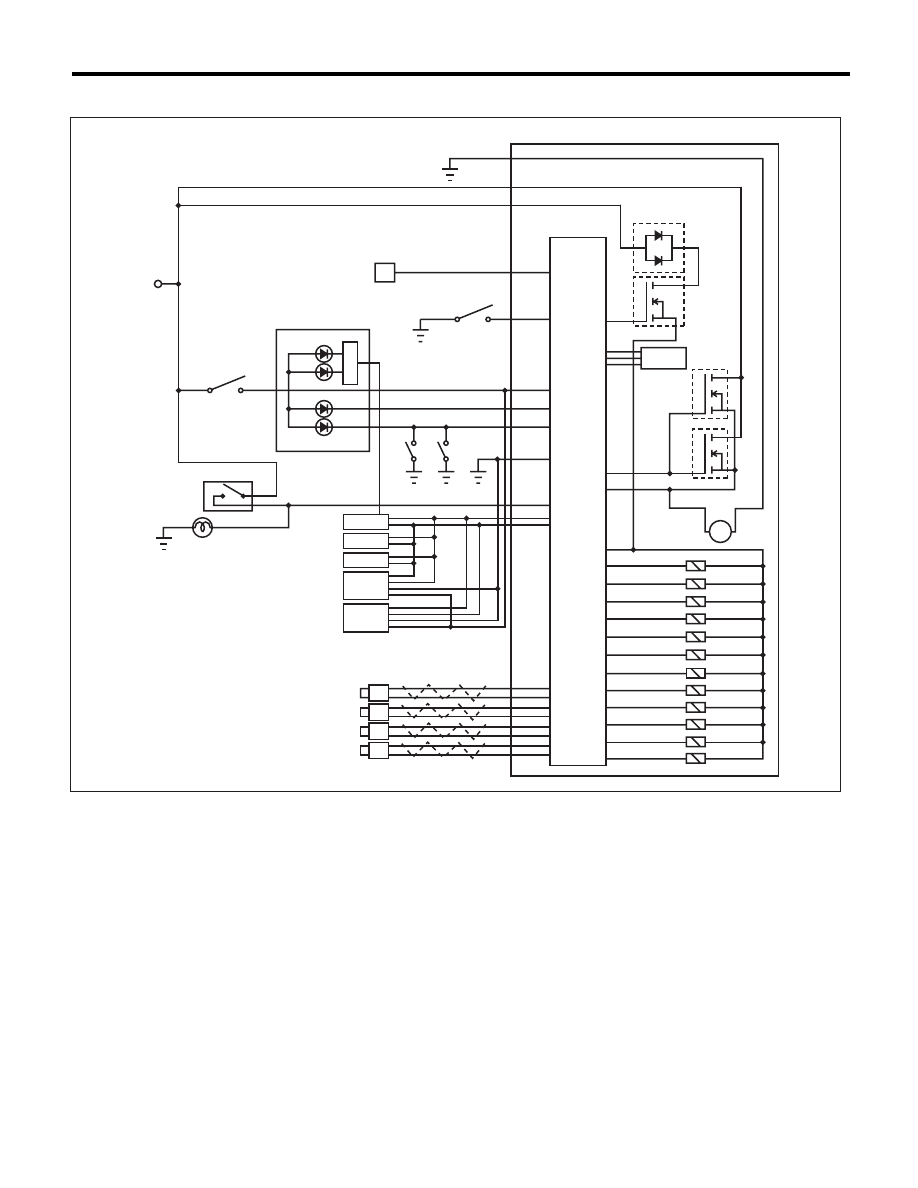
B: WIRING DIAGRAM
(1)
Battery
(14)
Rear inlet solenoid valve RH
(27)
Parking brake switch
(2)
Ignition switch
(15)
Rear outlet solenoid valve RH
(28)
Brake fluid level switch
(3)
VDC control module and hydraulic
control unit (VDCCM&H/U)
(16)
Primary cut solenoid valve
(29)
Stop light switch
(17)
Primary suction solenoid valve
(30)
Stop light
(4)
VDC control module
(18)
Secondary cut solenoid valve
(31)
Body integrated unit
(5)
Valve relay
(19)
Secondary suction solenoid valve
(32)
Engine control module (ECM)
(6)
Motor relay
(20)
Data link connector
(33)
Transmission control module (TCM)
(7)
Motor
(21)
VDC OFF switch
(34)
Steering angle sensor
(8)
Front inlet solenoid valve LH
(22)
Combination meter
(35)
Yaw rate & lateral G sensor
(9)
Front outlet solenoid valve LH
(23)
VDC indicator light
(36)
Pressure sensor
(10)
Front inlet solenoid valve RH
(24)
VDC warning light and VDC OFF
indicator light
(37)
Front ABS wheel speed sensor LH
(11)
Front outlet solenoid valve RH
(38)
Front ABS wheel speed sensor RH
(12)
Rear inlet solenoid valve LH
(25)
ABS warning light
(39)
Rear ABS wheel speed sensor LH
(13)
Rear outlet solenoid valve LH
(26)
Brake warning light
(40)
Rear ABS wheel speed sensor RH
(3)
(7)
(6)
(5)
(11)
M
(12)
(13)
(20)
(2)
(24)
(23)
(22)
(4)
(28)
(1)
(29)
(30)
(37)
(14)
(8)
(9)
(10)
(15)
(16)
(17)
(18)
(21)
(33)
(32)
(31)
(34)
(35)
(38)
(39)
(40)
(27)
(26)
(25)
(19)
(36)
VDC00458
VDC(diag)-14
Subaru Select Monitor
VEHICLE DYNAMICS CONTROL (VDC) (DIAGNOSTICS)
6. Subaru Select Monitor
A: OPERATION
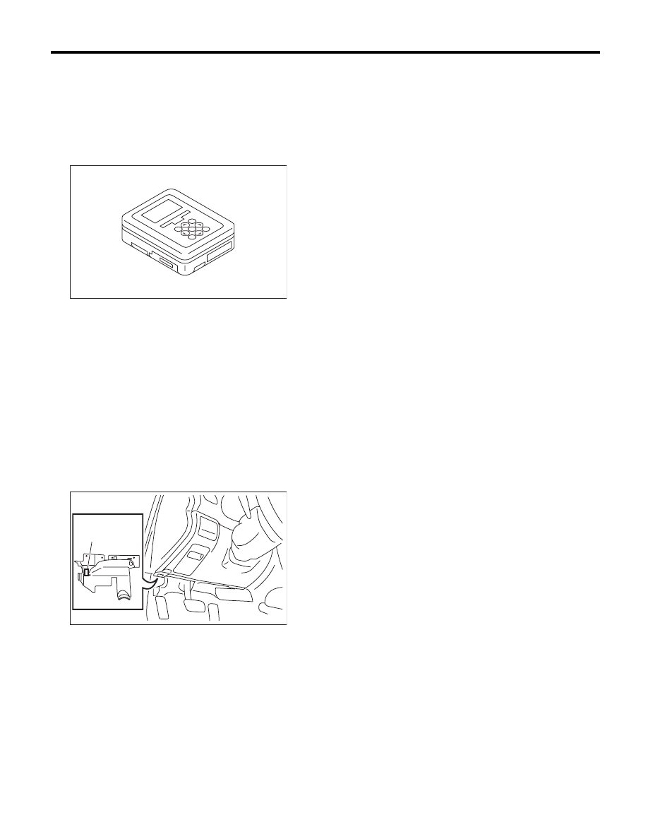
1. HOW TO USE SUBARU SELECT MONITOR
1) Prepare the Subaru Select Monitor kit. <Ref. to
VDC(diag)-8, SPECIAL TOOL, PREPARATION
TOOL, General Description.>
2) Prepare PC with Subaru Select Monitor in-
stalled.
3) Connect the USB cable between SDI (Subaru
Diagnosis Interface) and USB port on the personal
computer (dedicated port for the Subaru Select
Monitor).
NOTE:
The dedicated port for the Subaru Select Monitor
means the USB port which was used to install the
Subaru Select Monitor.
4) Connect the diagnosis cable to SDI.
5) Connect SDI to data link connector located in the
lower portion of the instrument panel (on the driv-
er’s side).
CAUTION:
Do not connect scan tools other than the Suba-
ru Select Monitor.
6) Start the PC.
7) Turn the ignition switch to ON (engine OFF) and
run the “PC application for Subaru Select Monitor”.
NOTE:
For detailed operation procedure, refer to the “PC
application help for Subaru Select Monitor”.
8) If VDC and Subaru Select Monitor cannot com-
municate, check the communication circuit. <Ref.
to VDC(diag)-18, COMMUNICATION FOR INI-
TIALIZING IMPOSSIBLE, INSPECTION, Subaru
Select Monitor.>
(1) Data link connector
EN-05692
ABS00465
(1)
Нет комментариевНе стесняйтесь поделиться с нами вашим ценным мнением.
Текст