Subaru Legacy IV (2008 year). Service manual — part 118

EN(H4SO)(diag)-75
Diagnostics for Engine Starting Failure
ENGINE (DIAGNOSTICS)
2
CHECK GROUND CIRCUIT OF FUEL PUMP.
1) Turn the ignition switch to OFF.
2) Remove the fuel pump access hole lid.
3) Disconnect the connector from fuel pump.
4) Measure the resistance of harness connec-
tor between fuel pump and chassis ground.
Connector & terminal
(R58) No. 6 — Chassis ground:
Is the resistance less than 5
:? Go to step 3.
Repair the harness
and connector.
NOTE:
In this case, repair
the following item:
• Open circuit in
harness between
fuel pump connec-
tor and chassis
grounding terminal
• Poor contact of
coupling connector
3
CHECK POWER SUPPLY TO FUEL PUMP.
1) Turn the ignition switch to ON.
2) Measure the voltage of power supply circuit
between fuel pump connector and chassis
ground.
Connector & terminal
(R58) No. 5 (+) — Chassis ground (–):
Is the voltage 10 V or more?
Replace the fuel
pump. <Ref. to
FU(H4SO)-55,
Fuel Pump.>
Go to step 4.
4
CHECK HARNESS BETWEEN FUEL PUMP
AND FUEL PUMP RELAY CONNECTOR.
1) Turn the ignition switch to OFF.
2) Measure the resistance of harness between
fuel pump connector and fuel pump relay con-
nector.
Connector & terminal
(R58) No. 5 — (B362) No. 2:
Is the resistance less than 1
:? Go to step 5.
Repair the harness
and connector.
NOTE:
In this case, repair
the following item:
• Open circuit in
harness between
fuel pump connec-
tor and fuel pump
relay connector
• Poor contact of
coupling connector
5
CHECK HARNESS BETWEEN FUEL PUMP
AND FUEL PUMP RELAY CONNECTOR.
Measure the resistance of harness between
fuel pump and fuel pump relay connector.
Connector & terminal
(R58) No. 5 — Chassis ground:
Is the resistance 1 M
: or
more?
Go to step 6.
Repair the short
circuit of harness
between fuel pump
connector and fuel
pump relay con-
nector.
6
CHECK FUEL PUMP RELAY.
1) Remove the fuel pump relay.
2) Connect the battery to fuel pump relay ter-
minals No. 3 and No. 4.
3) Measure the resistance between terminals
of fuel pump relay.
Terminals
No. 1 — No. 2:
Is the resistance less than 1
:? Go to step 7.
Replace the fuel
pump relay. <Ref.
to FU(H4SO)-41,
Fuel Pump Relay.>
7
CHECK HARNESS BETWEEN ECM AND
FUEL PUMP RELAY CONNECTOR.
1) Disconnect the connectors from ECM.
2) Measure the resistance of harness between
ECM and fuel pump relay connector.
Connector & terminal
(B136) No. 12 — (B362) No. 3:
Is the resistance less than 1
:? Go to step 8.
Repair the open
circuit of harness
between ECM and
fuel pump relay
connector.
8
CHECK POWER SUPPLY OF FUEL PUMP
RELAY.
1) Turn the ignition switch to ON.
2) Measure the voltage between fuel pump
relay connector and chassis ground.
Connector & terminal
(B362) No. 1 (+) — Chassis ground (–):
(B362) No. 4 (+) — Chassis ground (–):
Is the voltage 10 V or more?
Repair the poor
contact of ECM
connector.
Repair the open or
ground short circuit
of power supply
circuit.
Step
Check
Yes
No
EN(H4SO)(diag)-76
Diagnostics for Engine Starting Failure
ENGINE (DIAGNOSTICS)
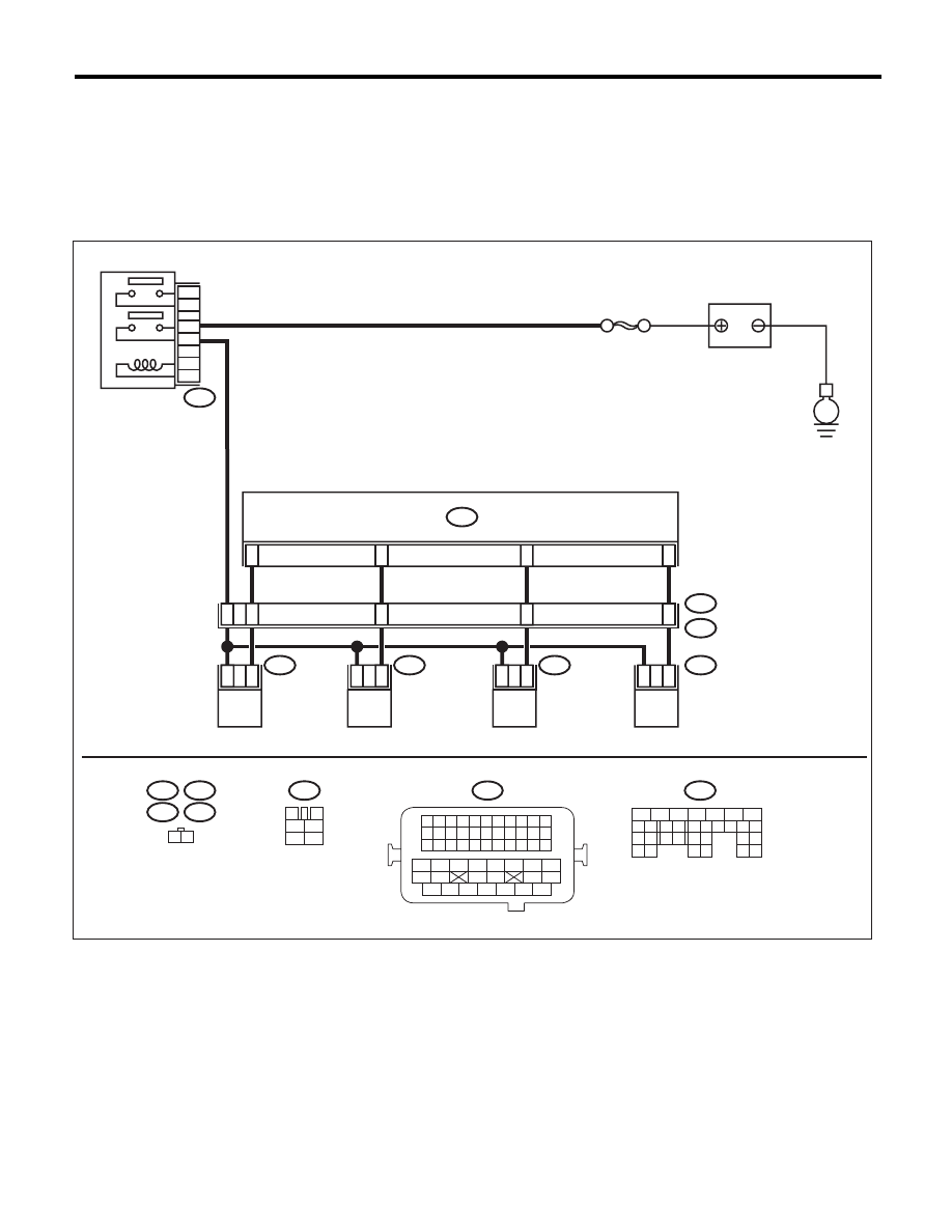
F: FUEL INJECTOR CIRCUIT
CAUTION:
• Check or repair only faulty parts.
• After repair or replacement of faulty parts, perform Clear Memory Mode <Ref. to EN(H4SO)(diag)-
50, OPERATION, Clear Memory Mode.>, and Inspection Mode <Ref. to EN(H4SO)(diag)-41, PROCE-
DURE, Inspection Mode.>.
WIRING DIAGRAM:
EN-06833
E6
E17
E5
E16
1 2
1
2
1
2
1
2
1
2
10
9
8
11
42
48
43
44
45
B137
E5
E16
E6
E17
B21
E2
SBF-7
B47
1
2
4
6
3
5
B47
3
4
1
2
5
6
E
B137
B21
1 2 3 4
12 13 14 15
5 6 7 8
16 17 18 19
9 10 11
20 21 22
23 24 25 26 27 28 29 30 31 32 33
35
34
37
36
39
38
41
40
43
42
44
45
47
46
49
48
51
50
53
52
54
ECM
FUEL INJECTOR
No. 1
MAIN RELAY
BATTERY
FUEL INJECTOR
No. 2
FUEL INJECTOR
No. 3
FUEL INJECTOR
No. 4
5
6
7
8
2
1
9
4
3
10
22 23
11 12 13 14 15
24 25
26
16 17
18 19 20 21
27
28 29
30 31

EN(H4SO)(diag)-77
Diagnostics for Engine Starting Failure
ENGINE (DIAGNOSTICS)
Step
Check
Yes
No
1
CHECK OPERATION OF EACH FUEL INJEC-
TOR.
While cranking the engine, check each fuel
injector emits operating sound. Use a sound
scope or attach a screwdriver to the injector to
listen to sounds for this check.
Does the fuel pump emit oper-
ating sound?
Check the fuel
pressure. <Ref. to
ME(H4SO)-26,
INSPECTION,
Fuel Pressure.>
Go to step 2.
2
CHECK POWER SUPPLY TO EACH FUEL IN-
JECTOR.
1) Turn the ignition switch to OFF.
2) Disconnect the connector from fuel injector.
3) Turn the ignition switch to ON.
4) Measure the voltage between fuel injector
connector and the engine ground.
Connector & terminal
#1 (E5) No. 2 (+) — Engine ground (–):
#2 (E16) No. 2 (+) — Engine ground (–):
#3 (E6) No. 2 (+) — Engine ground (–):
#4 (E17) No. 2 (+) — Engine ground (–):
Is the voltage 10 V or more?
Go to step 3.
Repair the harness
and connector.
NOTE:
In this case, repair
the following item:
• Open circuit in
harness between
main relay connec-
tor and fuel injector
connector
• Poor contact of
main relay connec-
tor
• Poor contact of
coupling connector
3
CHECK HARNESS BETWEEN ECM AND
FUEL INJECTOR CONNECTOR.
1) Disconnect the connectors from ECM.
2) Measure the resistance of harness between
ECM and fuel injector connector.
Connector & terminal
(B137) No. 8 — (E5) No. 1:
(B137) No. 9 — (E16) No. 1:
(B137) No. 10 — (E6) No. 1:
(B137) No. 11 — (E17) No. 1:
Is the resistance less than 1
:? Go to step 4.
Repair the harness
and connector.
NOTE:
In this case, repair
the following item:
• Open circuit of
harness between
ECM and fuel in-
jector connector
• Poor contact of
coupling connector
4
CHECK HARNESS BETWEEN ECM AND
FUEL INJECTOR CONNECTOR.
Measure the resistance between ECM and
chassis ground.
Connector & terminal
#1 (B137) No. 8 — Chassis ground:
#2 (B137) No. 9 — Chassis ground:
#3 (B137) No. 10 — Chassis ground:
#4 (B137) No. 11 — Chassis ground:
Is the resistance 1 M
: or
more?
Go to step 5.
Repair the short
circuit to ground in
harness between
ECM and fuel
injector connector.
<Ref. to
FU(H4SO)-30,
Fuel Injector.>
5
CHECK EACH FUEL INJECTOR.
1) Turn the ignition switch to OFF.
2) Measure the resistance between each fuel
injector terminals.
Terminals
No. 1 — No. 2:
Is the resistance between 5 —
20
:?
Go to step 6.
Replace the faulty
fuel injector. <Ref.
to FU(H4SO)-30,
Fuel Injector.>
6
CHECK POOR CONTACT.
Check for poor contact of the ECM connector.
Is there poor contact in ECM
connector?
Repair the poor
contact of ECM
connector.
Inspection using
“General Diagnos-
tic Table”<Ref. to
EN(H4SO)(diag)-
300, INSPEC-
TION, General
Diagnostic Table.>
EN(H4SO)(diag)-78
Diagnostic Procedure for Subaru Select Monitor Communication
ENGINE (DIAGNOSTICS)
18.Diagnostic Procedure for Subaru Select Monitor Communication
A: COMMUNICATION FOR INITIALIZING IMPOSSIBLE
DIAGNOSIS:
Open or short circuit in data link connector
TROUBLE SYMPTOM:
Subaru Select Monitor communication failure
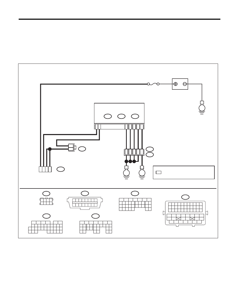
WIRING DIAGRAM:
EN-06834
: TERMINAL No. OPTIONAL ARRANGEMENT
*
No. 13
E
BATTERY
B40
1 2 3 4 5 6 7 8
9 10 11 12 13 14 15 16
B21
1 2 3 4 5 6 7 8 9 10 11
12 13 14 15 16 17 18 19 20 21 22
23 24 25 26 27 28 29 30 31 32 33
34
35
42
43
36
37
38
39
48
49
50
51
52
53
54
40
41
44
45
46
47
B40
DATA LINK
CONNECTOR
4
5
7
16
B122
*
*
1 2 3 4
5 6 7 8
B122
16
10 11 12 13 14 15
25
24
30
9
8
7
17 18 19 20
28
21 22 23
29
32
31
1
2
3
4
5
6
27
26
33 34 35
B136
C:
5
6
7
8
2
1
9
4
3
10
24
22 23
25
11 12 13 14 15
26 27
28
16 17
18 19 20 21
33 34
29
32
30 31
B134
A:
5
6
7
8
2
1
9
4
3
10
22 23
11 12 13 14 15
24 25
26
16 17
18 19 20 21
27
28 29
30 31
B137
D:
D1
D2
D3
E2
B21
E
ECM
B134
A:
C: B136
D: B137
D7
E
A5
C6
C16
34
36
52
35
37
Нет комментариевНе стесняйтесь поделиться с нами вашим ценным мнением.
Текст