Subaru Legacy IV (2008 year). Service manual — part 116

EN(H4SO)(diag)-67
Diagnostics for Engine Starting Failure
ENGINE (DIAGNOSTICS)
7
CHECK INPUT VOLTAGE OF STARTER RE-
LAY.
1) Turn the ignition switch to OFF.
2) Disconnect the connector from starter relay.
3) Connect the connector to ignition switch.
4) Measure the input voltage between starter
relay connector and chassis ground after turn-
ing the ignition switch to START position.
Connector & terminal
(B225) No. 13 (+) — Chassis ground (–):
(B225) No. 15 (+) — Chassis ground (–):
Is the voltage 10 V or more?
Go to step 8.
Check the follow-
ing item and repair
if necessary.
• Blown out of fuse
• Open or short
circuit to ground in
harness between
starter relay and
ignition switch con-
nector
8
CHECK STARTER RELAY.
1) Connect the battery to starter relay termi-
nals No. 15 and No. 16.
2) Measure the resistance between starter
relay terminals.
Terminals
No. 13 — No. 14:
Is the resistance less than 1
:? Go to step 9.
Replace the starter
relay.
9
CHECK HARNESS BETWEEN ECM AND
STARTER RELAY.
1) Disconnect the connectors from ECM.
2) Measure the resistance of harness connec-
tor between ECM and starter relay.
Connector & terminal
(B225) No. 16 — (B136) No. 20:
Is the resistance less than 1
:? Go to step 10.
Repair the open
circuit of harness
between ECM and
starter relay con-
nector.
10
CHECK TRANSMISSION TYPE.
Is the transmission type AT?
Go to step 11.
Go to step 15.
11
CHECK ECM INPUT VOLTAGE.
1) Turn the ignition switch to START.
2) Measure the input voltage between ECM
and chassis ground.
Connector & terminal
(B136) No. 32 (+) — Chassis ground (–):
Is the voltage 10 V or more?
Go to step 12.
Repair the open
circuit of harness
between ECM and
ignition switch con-
nector.
12
CHECK HARNESS BETWEEN STARTER RE-
LAY AND INHIBITOR SWITCH.
1) Turn the ignition switch to OFF.
2) Disconnect the connector from inhibitor
switch.
3) Measure the resistance of harness between
the starter relay and inhibitor switch.
Connector & terminal
(B225) No. 14 — (T7) No. 9:
Is the resistance less than 1
:? Go to step 13.
Repair the harness
and connector.
NOTE:
In this case, repair
the following item:
• Open circuit in
harness between
starter relay con-
nector and inhibitor
switch connector
• Poor contact of
coupling connector
13
CHECK HARNESS BETWEEN INHIBITOR
SWITCH AND STARTER MOTOR.
Measure the resistance of harness between the
inhibitor switch and starter motor.
Connector & terminal
(T7) No. 6 — (B14) No. 1:
Is the resistance less than 1
:? Go to step 14.
Repair the harness
and connector.
NOTE:
In this case, repair
the following item:
• Open circuit in
harness between
inhibitor switch
connector and
starter motor
• Poor contact of
coupling connector
Step
Check
Yes
No

EN(H4SO)(diag)-68
Diagnostics for Engine Starting Failure
ENGINE (DIAGNOSTICS)
14
CHECK INHIBITOR SWITCH.
1) Place the select lever in “P” range or “N”
range.
2) Measure the resistance between inhibitor
switch terminals.
Terminals
No. 6 — No. 9:
Is the resistance less than 1
:? Check the engine
control module
(ECM) power sup-
ply and ground
line. <Ref. to
EN(H4SO)(diag)-
69, CHECK
POWER SUPPLY
AND GROUND
LINE OF ENGINE
CONTROL MOD-
ULE (ECM), Diag-
nostics for Engine
Starting Failure.>
Replace the inhibi-
tor switch. <Ref. to
4AT-46, Inhibitor
Switch.>
15
CHECK HARNESS BETWEEN IGNITION
SWITCH AND CLUTCH START SWITCH.
1) Turn the ignition switch to OFF.
2) Disconnect the connector from clutch start
switch.
3) Turn the ignition switch to START.
4) Measure the voltage between the clutch
start switch and chassis ground.
Connector & terminal
(B106) No. 1 (+) — Chassis ground (–):
Is the voltage 10 V or more?
Go to step 16.
Repair the open
circuit in harness
between ignition
switch connector
and clutch start
switch.
16
CHECK CLUTCH START SWITCH.
Measure the resistance between clutch start
switch terminals while depressing the clutch
pedal.
Terminals
No. 1 — No. 2:
Is the resistance less than 1
:? Go to step 17.
Replace the clutch
start switch. <Ref.
to CL-37, Clutch
Switch.>
17
CHECK HARNESS BETWEEN ECM AND
CLUTCH START SWITCH.
Measure the resistance of harness between
ECM and clutch start switch.
Connector & terminal
(B136) No. 32 — (B106) No. 2:
Is the resistance less than 1
:? Go to step 18.
Repair the open
circuit of harness
between the ECM
and clutch start
switch.
18
CHECK HARNESS BETWEEN STARTER RE-
LAY AND STARTER MOTOR.
Measure the resistance of harness between
starter relay connector and starter motor.
Connector & terminal
(B225) No. 14 — (B14) No. 1:
Is the resistance less than 1
:? Check the engine
control module
(ECM) power sup-
ply and ground
line. <Ref. to
EN(H4SO)(diag)-
69, CHECK
POWER SUPPLY
AND GROUND
LINE OF ENGINE
CONTROL MOD-
ULE (ECM), Diag-
nostics for Engine
Starting Failure.>
Repair the open
circuit of the har-
ness between
starter relay con-
nector and starter
motor.
Step
Check
Yes
No
EN(H4SO)(diag)-69
Diagnostics for Engine Starting Failure
ENGINE (DIAGNOSTICS)
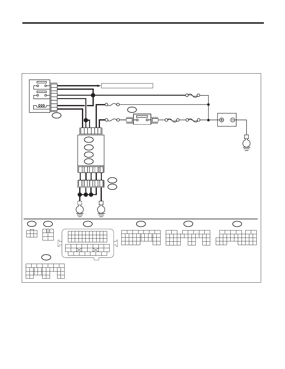
C: CHECK POWER SUPPLY AND GROUND LINE OF ENGINE CONTROL MODULE
(ECM)
CAUTION:
After repair or replacement of faulty parts, perform Clear Memory Mode <Ref. to EN(H4SO)(diag)-50,
OPERATION, Clear Memory Mode.>, and Inspection Mode <Ref. to EN(H4SO)(diag)-41, PROCEDURE,
Inspection Mode.>.
WIRING DIAGRAM:
EN-06831
SBF-6
MAIN SBF
SBF-7
B72
No. 12
B47
E2
B21
2
1
4
6
5
3
E
3
1
B134
B135
A:
D: B137
C: B136
B:
3
4
1
2
5
6
B47
No. 13
B134
5
6
7
8
2
1
9
4
3
10
24
22 23
25
11 12 13 14 15
26 27
28
16 17
18 19 20 21
33 34
29
32
30 31
B135
5
6
7
8
2
1
9
4
3
10
24
22 23
25
11 12 13 14 15
26 27
28
16 17 18 19
20 21
29 30 31
32 33
34 35
B137
5
6
7
8
2
1
9
4
3
10
22 23
11 12 13 14 15
24 25
26
16 17
18 19 20 21
27
28 29
30 31
B21
1 2 3 4
12 13 14 15
5 6 7 8
16 17 18 19
9 10 11
20 21 22
23 24 25 26 27 28 29 30 31 32 33
35
34
37
36
39
38
41
40
43
42
44
45
47
46
49
48
51
50
53
52
54
B72
1
3
4 5 6
2
A:
B:
D:
MAIN RELAY
ECM
TO IGNITION COIL & IGNITOR ASSY
BATTERY
IGNITION
SWITCH
A7
B2
C23
B19
A5
D2
D1
D3
B5
36
34
37
35
D7
52
16
10 11 12 13 14 15
25
24
30
9
8
7
17 18 19 20
28
21 22 23
29
32
31
1
2
3
4
5
6
27
26
33 34 35
B136
C:
E
E

EN(H4SO)(diag)-70
Diagnostics for Engine Starting Failure
ENGINE (DIAGNOSTICS)
Step
Check
Yes
No
1
CHECK MAIN RELAY.
1) Turn the ignition switch to OFF.
2) Remove the main relay.
3) Connect the battery to main relay terminals
No. 1 and No. 2.
4) Measure the resistance between main relay
terminals.
Terminals
No. 3 — No. 5:
No. 4 — No. 6:
Is the resistance less than 1
:? Go to step 2.
Replace the main
relay. <Ref. to
FU(H4SO)-40,
Main Relay.>
2
CHECK GROUND CIRCUIT FOR ECM.
1) Disconnect the connectors from ECM.
2) Measure the resistance of harness between
ECM and chassis ground.
Connector & terminal
(B134) No. 5 — Chassis ground:
(B137) No. 1 — Chassis ground:
(B137) No. 2 — Chassis ground:
(B137) No. 3 — Chassis ground:
(B137) No. 7 — Chassis ground:
Is the resistance less than 5
:? Go to step 3.
Repair the harness
and connector.
NOTE:
In this case, repair
the following item:
• Open circuit of
harness between
ECM and engine
ground
• Poor contact of
coupling connector
3
CHECK INPUT VOLTAGE OF ECM.
1) Turn the ignition switch to ON.
2) Measure the voltage between ECM connec-
tor and chassis ground.
Connector & terminal
(B135) No. 5 (+) — Chassis ground (–):
(B135) No. 19 (+) — Chassis ground (–):
Is the voltage 10 V or more?
Go to step 4.
Repair the open or
ground short circuit
of harness of
power supply cir-
cuit.
4
CHECK INPUT VOLTAGE OF MAIN RELAY.
Measure the voltage between main relay con-
nector and chassis ground.
Connector & terminal
(B47) No. 2 (+) — Chassis ground (–):
(B47) No. 5 (+) — Chassis ground (–):
(B47) No. 6 (+) — Chassis ground (–):
Is the voltage 10 V or more?
Go to step 5.
Repair the open or
ground short circuit
of harness of
power supply cir-
cuit.
5
CHECK INPUT VOLTAGE OF ECM.
1) Turn the ignition switch to OFF.
2) Install the main relay.
3) Turn the ignition switch to ON.
4) Measure the voltage between ECM connec-
tor and chassis ground.
Connector & terminal
(B136) No. 23 (+) — Chassis ground (–):
Is the voltage 10 V or more?
Go to step 6.
Repair the open or
ground short circuit
of harness
between ECM and
main relay connec-
tor.
6
CHECK INPUT VOLTAGE OF ECM.
1) Turn the ignition switch to OFF.
2) Connect the connector to ECM.
3) Turn the ignition switch to ON.
4) Measure the voltage between ECM connec-
tor and chassis ground.
Connector & terminal
(B134) No. 7 (+) — Chassis ground (–):
(B135) No. 2 (+) — Chassis ground (–):
Is the voltage 10 V or more?
Check ignition con-
trol system. <Ref.
to
EN(H4SO)(diag)-
71, IGNITION
CONTROL SYS-
TEM, Diagnostics
for Engine Starting
Failure.>
Repair the harness
and connector.
NOTE:
In this case, repair
the following item:
• Open circuit in
harness between
ECM and main re-
lay connector
• Poor contact of
main relay connec-
tor
Нет комментариевНе стесняйтесь поделиться с нами вашим ценным мнением.
Текст