Subaru Legacy IV (2008 year). Service manual — part 89
LU(H4SO)-13
Oil Pump
LUBRICATION
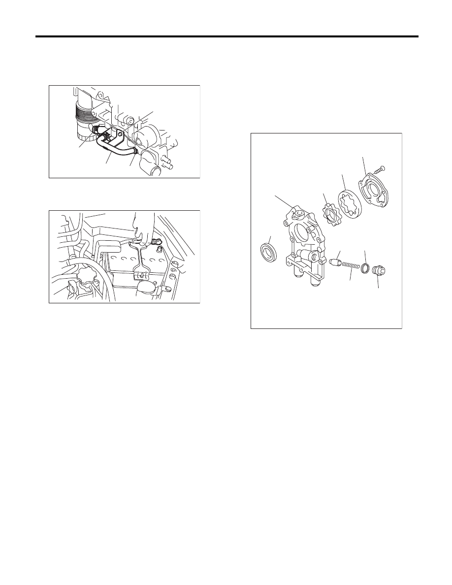
12) Install the oil cooler pipe (A) to the oil pump us-
ing the bolt (B). (Turbo model)
Tightening torque:
6.4 N·m (0.7 kgf-m, 4.7 ft-lb)
13) Install the under cover.
14) Lower the vehicle.
15) Connect the ground cable to battery.
16) Install the collector cover. (Turbo model)
C: DISASSEMBLY
Remove the screw which secures oil pump cover
and then disassemble oil pump. Inscribe alignment
marks on the inner and outer rotors so that they can
be replaced in their original positions during reas-
sembly.
NOTE:
Before disassembling the oil pump, remove the re-
lief valve.
LU-02396
(B)
(C)
(C)
(A)
IN-00203
(A) Front oil seal
(B) Oil pump case
(C) Inner rotor
(D) Outer rotor
(E) Oil pump cover
(F) Relief valve
(G) Relief valve spring
(H) Plug
(I) Gasket
LU-00020
(E)
(D)
(C)
(B)
(A)
(F)
(G)
(I)
(H)
LU(H4SO)-14
Oil Pump
LUBRICATION
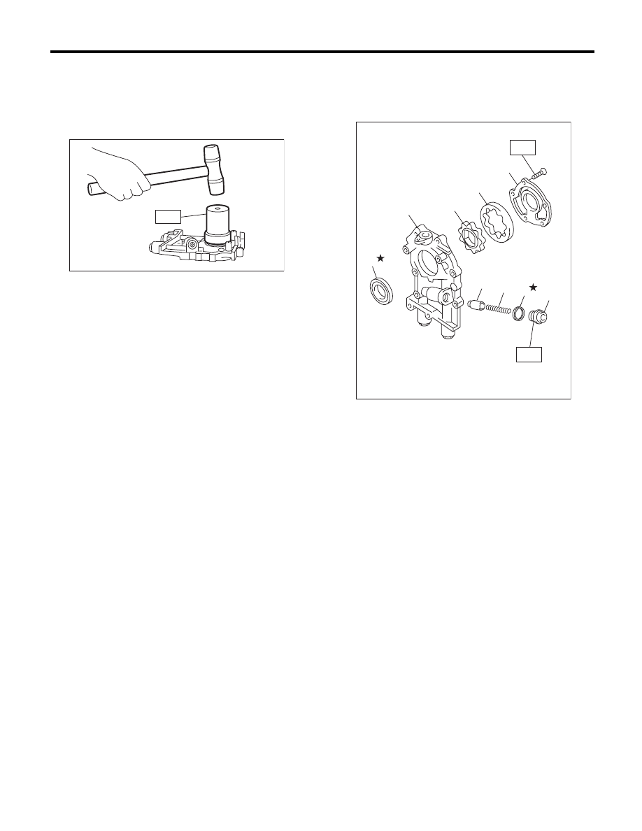
D: ASSEMBLY
1) Using the ST, install the front oil seal.
ST
499587100
OIL SEAL INSTALLER
NOTE:
Use a new front oil seal.
2) Apply a coat of engine oil to inner and outer ro-
tors.
3) Assemble the inner and outer rotors in their orig-
inal positions.
4) Assemble the oil relief valve and install relief
valve spring and plug.
NOTE:
Use a new gasket.
5) Install the oil pump cover.
Tightening torque:
T1: 5.4 N·m (0.6 kgf-m, 4.0 ft-lb)
T2: 44 N·m (4.5 kgf-m, 32.5 ft-lb)
LU-00021
ST
(A) Front oil seal
(B) Oil pump case
(C) Inner rotor
(D) Outer rotor
(E) Oil pump cover
(F) Relief valve
(G) Relief valve spring
(H) Plug
(I) Gasket
LU-02134
T1
T2
(G)
(F)
(I)
(H)
(A)
(B)
(C)
(D)
(E)
LU(H4SO)-15
Oil Pump
LUBRICATION
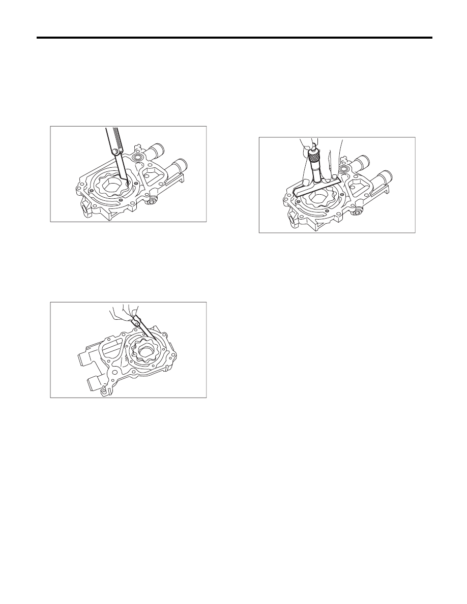
E: INSPECTION
1. TIP CLEARANCE
Measure the tip clearance of rotors. If the clearance
is out of specification, replace the rotors as a set.
Tip clearance:
Standard
0.04 — 0.14 mm (0.0016 — 0.0055 in)
2. CASE CLEARANCE
Measure the clearance between the outer rotor and
the oil pump case. If clearance is out of standard,
replace the oil pump case.
Case clearance:
Standard
0.10 — 0.175 mm (0.0039 — 0.0069 in)
3. SIDE CLEARANCE
Measure the gap between the inner rotor and the
oil pump case to measure the clearance between
the oil pump inner rotor and the oil pump cover as
shown in the figure. If the clearance is out of spec-
ification, replace the rotors or the oil pump case.
Side clearance:
Standard
0.02 — 0.07 mm (0.0008 — 0.0028 in)
4. OIL RELIEF VALVE
Check the valve for assembly condition and dam-
age, and the relief valve spring for damage and de-
terioration. Replace the parts if defective.
Relief valve spring:
Free length
73.7 mm (2.902 in)
Installed length
54.7 mm (2.154 in)
Load when installed
93.1 N (9.49 kgf, 20.88 lbf)
5. OIL PUMP CASE
Check for worn shaft hole, clogged oil passage,
worn rotor chamber, cracks and other faults.
6. FRONT OIL SEAL
Check the front oil seal lips for deformation, hard-
ening, wear, etc. and replace if defective.
LU-00023
LU-00024
LU-00025
LU(H4SO)-16
Oil Pan and Strainer
LUBRICATION
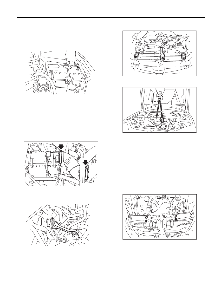
5. Oil Pan and Strainer
A: REMOVAL
1) Set the vehicle on a lift.
2) Remove the collector cover. (Turbo model)
3) Disconnect the ground cable from battery.
4) Remove the air intake duct. <Ref. to IN(H4SO)-
8, REMOVAL, Air Intake Duct.> <Ref. to
IN(H4DOTC)-9, REMOVAL, Air Intake Duct.>
5) Disconnect the connector from the mass air flow
and intake air temperature sensor. (Non-turbo
model)
6) Remove the air intake chamber. (Non-turbo
model) <Ref. to IN(H4SO)-7, REMOVAL, Air Intake
Chamber.>
7) Remove the air intake boot. (Turbo model)
8) Remove the intercooler. (Turbo model) <Ref. to
IN(H4DOTC)-12, REMOVAL, Intercooler.>
9) Remove the pitching stopper.
10) Remove the hood stay holder (A) and radiator
upper brackets (B).
11) Support the engine with a lifting device and
wire ropes.
12) Lift up the vehicle.
CAUTION:
When lifting up the vehicle, raise up wire ropes
at the same time.
13) Remove the under cover.
14) Drain the engine oil. <Ref. to LU(H4SO)-10,
REPLACEMENT, Engine Oil.>
15) Remove the front exhaust pipe. <Ref. to
EX(H4SO)-4, REMOVAL, Front Exhaust Pipe.>
<Ref. to EX(H4DOTC)-5, REMOVAL, Front Ex-
haust Pipe.>
16) Remove the nuts which install the engine
mounting onto the front crossmember.
17) Remove the bolts which install oil pan on cylin-
der block with the engine raised up.
IN-00203
LU-02397
AT-03877
LU-00232
(A)
(B)
(B)
LU-00222
ME-02650
Нет комментариевНе стесняйтесь поделиться с нами вашим ценным мнением.
Текст