Subaru Legacy IV (2008 year). Service manual — part 87
LU(H4SO)-5
General Description
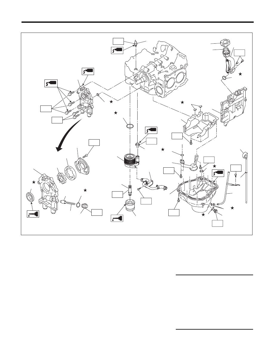
LUBRICATION
• TURBO MODEL
(1)
Plug
(16)
Oil pressure switch
(31)
Seal
(2)
Gasket
(17)
Oil filler duct
(32)
O-ring
(3)
Relief valve spring
(18)
O-ring
(33)
Gasket
(4)
Relief valve
(19)
Rocker cover
(34)
O-ring
(5)
Front oil seal
(20)
Baffle plate
(35)
Nipple
(6)
Oil pump case
(21)
O-ring
(7)
Inner rotor
(22)
Oil strainer
Tightening torque:N·m (kgf-m, ft-lb)
(8)
Outer rotor
(23)
Gasket
T1: 5 (0.5, 3.7)
(9)
Oil pump cover
(24)
Oil level gauge guide
T2: 5.4 (0.6, 4.0)
(10)
Oil filter
(25)
Oil pan
T3: 6.4 (0.7, 4.7)
(11)
Oil cooler connector
(26)
Oil level gauge
T4: 10 (1.0, 7.4)
(12)
Water by-pass pipe
(27)
Drain plug gasket
T5: 25 (2.5, 18.4)
(13)
Oil cooler
(28)
Drain plug
T6: 44 (4.5, 32.5)
(14)
O-ring
(29)
Gasket
T7: 54 (5.5, 39.8)
(15)
Oil pump ASSY
(30)
Oil filler cap
T8: 69 (7.0, 50.9)
LU-02422
(15)
(14)
T5
T3
T2
T6
(9)
(8)
(7)
(6)
(16)
(26)
(5)
(4)
(3)
(2)
(1)
(29)
(19)
T7
(11)
(12)
(10)
T3
(13)
T8
T6
(28)
(25)
(27)
(23)
T1
T3
(24)
(32)
T3
(20)
(31)
T4
(22)
(21)
T3
(18)
(17)
(30)
(33)
T3
(34)
T3
(35)
LU(H4SO)-6
General Description
LUBRICATION
C: CAUTION
• Wear appropriate work clothing, including a cap, protective goggles and protective shoes when performing
any work.
• Remove contamination including dirt and corrosion before removal, installation or disassembly.
• Keep the disassembled parts in order and protect them from dust and dirt.
• Before removal, installation or disassembly, be sure to clarify the failure. Avoid unnecessary removal, in-
stallation, disassembly and replacement.
• Be careful not to burn your hands, because each part on the vehicle is hot after running.
• Be sure to tighten fasteners including bolts and nuts to the specified torque.
• Place shop jacks or rigid racks at the specified points.
• Before disconnecting connectors of sensors or units, be sure to disconnect the ground cable from battery.
• If the engine oil is spilt over exhaust pipe or the under cover, wipe it off with cloth to avoid emitting smoke
or causing a fire.
• Prepare a container and cloth to prevent scattering of oil when performing work where fuels can be spilled.
If the fuel spills, wipe it off immediately to prevent from penetrating into floor or flowing out for environmental
protection.
• Follow all government and local regulations concerning disposal of refuse when disposing oil.
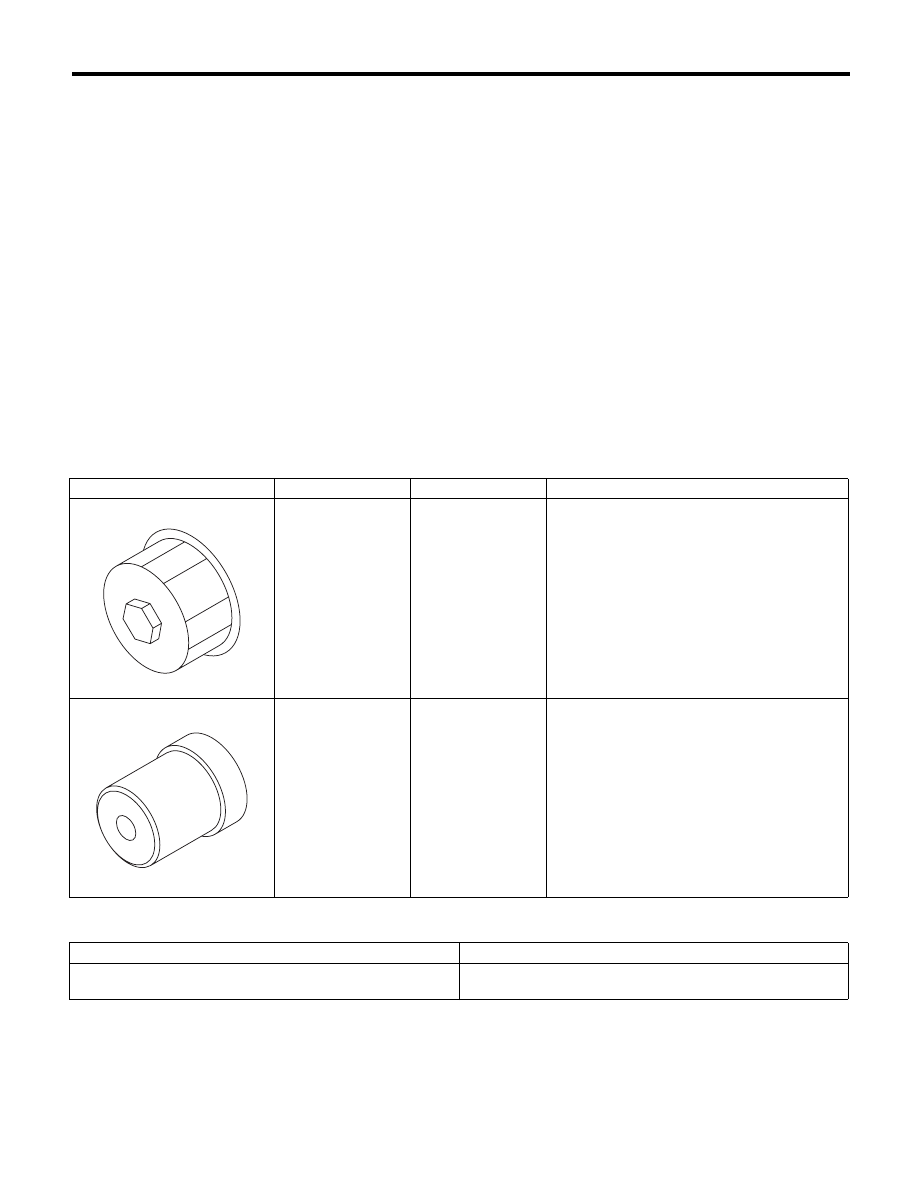
D: PREPARATION TOOL
1. SPECIAL TOOL
2. GENERAL TOOL
ILLUSTRATION
TOOL NUMBER
DESCRIPTION
REMARKS
18332AA000
OIL FILTER
WRENCH
Used for removing and installing oil filter (Black).
(Outer diameter: 68 mm (2.68 in))
499587100
OIL SEAL
INSTALLER
Used for installing oil seal into oil pump.
TOOL NAME
REMARKS
Oil filter wrench (65/67 mm 14 Flutes)
Used for removing and installing oil filter (Blue).
(Outer diameter: 67.4 mm (2.65 in))
ST18332AA000
ST-499587100
LU(H4SO)-7
Oil Pressure System
LUBRICATION
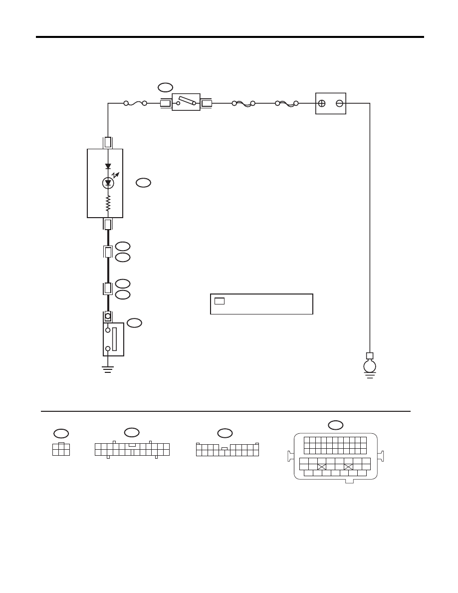
2. Oil Pressure System
A: WIRING DIAGRAM
E
i3
B38
B21
E2
17
E11
No. 5
SBF-6
MAIN SBF
B72
3
1
B72
A15
i10
i10
A3
1
3
4 5 6
2
2
1
3 4
6 7 8 9 10
22
21
20
19
18
17
16
15
14
13
12
11
5
1 2 3 4
5 6 7 8 9
10 11 12 13 14 15 16 17 18 19 20
B38
B21
1 2 3 4
12 13 14 15
5 6 7 8
16 17 18 19
9 10 11
20 21 22
23 24 25 26 27 28 29 30 31 32 33
35
34
37
36
39
38
41
40
43
42
44
45
47
46
49
48
51
50
53
52
54
A:
A:
BATTERY
IGNITION
SWITCH
COMBINATION
METER
OIL PRESSURE
W
ARNING LIGHT
OIL PRESSURE
SWITCH
LU-02478
*
: TURBO MODEL
: 45
*
EXCEPT FOR TURBO MODEL
: 31

LU(H4SO)-8
Oil Pressure System
LUBRICATION
B: INSPECTION
Step
Check
Yes
No
1
CHECK COMBINATION METER.
1) Turn the ignition switch to ON (engine OFF).
2) Check other warning lights.
Does the warning light illumi-
nate?
Go to step 2.
Repair or replace
the combination
meter. <Ref. to IDI-
5, INSPECTION,
Combination Meter
System.>
2
CHECK THE HARNESS CONNECTOR BE-
TWEEN THE COMBINATION METER AND
THE OIL PRESSURE SWITCH.
1) Turn the ignition switch to OFF.
2) Disconnect the connector from oil pressure
switch.
3) Turn the ignition switch to ON.
4) Measure the voltage of harness between oil
pressure switch connector and chassis ground.
Connector & terminal
(E11) No. 1 (+) — Chassis ground (–):
Is the voltage 10 V or more?
Replace the oil
pressure switch.
Go to step 3.
3
CHECK COMBINATION METER.
1) Turn the ignition switch to OFF.
2) Remove the combination meter.
3) Measure the resistance of combination
meter.
Terminals
(i10) No. 3 — No. 15:
Is the resistance less than 10
:? Repair the harness
and connector.
NOTE:
In this case, repair
the following item:
• Open circuit of
harness between
combination meter
and oil pressure
switch
• Poor contact in
combination meter
connector
• Poor contact of
coupling connector
Repair or replace
the combination
meter. <Ref. to IDI-
5, INSPECTION,
Combination Meter
System.>
Нет комментариевНе стесняйтесь поделиться с нами вашим ценным мнением.
Текст