Subaru Legacy IV (2008 year). Service manual — part 945

VDC(diag)-95
Diagnostic Procedure with Diagnostic Trouble Code (DTC)
VEHICLE DYNAMICS CONTROL (VDC) (DIAGNOSTICS)
2
CHECK YAW RATE & LATERAL G SENSOR
GROUND CIRCUIT.
Measure the resistance between the yaw rate &
lateral G sensor and chassis ground.
Connector & terminal
(B230) No. 4 — Chassis ground:
Is the resistance less than 0.5
:? Go to step 3.
Repair the ground
circuit of the yaw
rate & lateral G
sensor.
3
CHECK YAW RATE & LATERAL G SENSOR
HARNESS.
1) Disconnect the connector from the
VDCCM&H/U.
2) Measure the resistance between VDCCM&
H/U and yaw rate & lateral G sensor.
Connector & terminal
(B230) No. 3 — (B310) No. 10:
(B230) No. 2 — (B310) No. 35:
Is the resistance less than 0.5
:? Go to step 4.
Repair the harness
between yaw rate
& lateral G sensor
and VDCCM& H/U.
4
CHECK GROUND SHORT CIRCUIT FOR
YAW RATE & LATERAL G SENSOR HAR-
NESS.
Measure the resistance between the yaw rate &
lateral G sensor and chassis ground.
Connector & terminal
(B230) No. 2 — Chassis ground:
(B230) No. 3 — Chassis ground:
Is the resistance 1 M
: or
more?
Go to step 5.
Repair the harness
between yaw rate
& lateral G sensor
and VDCCM& H/U.
5
CHECK YAW RATE & LATERAL G SENSOR.
1) Turn the ignition switch to OFF.
2) Connect all connectors.
3) Clear the memory. <Ref. to VDC(diag)-23,
Clear Memory Mode.>
4) Perform the Inspection Mode. <Ref. to
VDC(diag)-22, Inspection Mode.>
5) Read the DTC.
Is the same DTC displayed?
Go to step 6.
Go to step 7.
6
CHECK YAW RATE & LATERAL G SENSOR.
1) Turn the ignition switch to OFF.
2) Replace the yaw rate & lateral G sensor.
3) Clear the memory. <Ref. to VDC(diag)-23,
Clear Memory Mode.>
4) Perform the Inspection Mode. <Ref. to
VDC(diag)-22, Inspection Mode.>
5) Read the DTC.
Is the same DTC displayed?
Replace the
VDCCM only.
<Ref. to VDC-10,
REPLACEMENT,
VDC Control Mod-
ule and Hydraulic
Control Unit
(VDCCM&H/U).>
Go to step 8.
7
CHECK OTHER DTC DETECTION.
Is any other DTC displayed?
Perform the diag-
nosis according to
DTC. <Ref. to
VDC(diag)-34, List
of Diagnostic Trou-
ble Code (DTC).>
Temporary poor
contact occurs.
8
CHECK OTHER DTC DETECTION.
Is any other DTC displayed?
Perform the diag-
nosis according to
DTC. <Ref. to
VDC(diag)-34, List
of Diagnostic Trou-
ble Code (DTC).>
Malfunction is
found in original
yaw rate & lateral
G sensor.
Step
Check
Yes
No
VDC(diag)-96
Diagnostic Procedure with Diagnostic Trouble Code (DTC)
VEHICLE DYNAMICS CONTROL (VDC) (DIAGNOSTICS)
AW:DTC C0073 LATERAL G SENSOR OFFSET IS TOO BIG
NOTE:
For the diagnostic procedure, refer to DTC C0073 “EXCESSIVE LATERAL G SENSOR SIGNAL”. <Ref. to
VDC(diag)-97, DTC C0073 EXCESSIVE LATERAL G SENSOR SIGNAL, Diagnostic Procedure with Diag-
nostic Trouble Code (DTC).>
AX:DTC C0073 ABNORMAL LATERAL G SENSOR OUTPUT
NOTE:
For the diagnostic procedure, refer to DTC C0073 “EXCESSIVE LATERAL G SENSOR SIGNAL”. <Ref. to
VDC(diag)-97, DTC C0073 EXCESSIVE LATERAL G SENSOR SIGNAL, Diagnostic Procedure with Diag-
nostic Trouble Code (DTC).>
VDC(diag)-97
Diagnostic Procedure with Diagnostic Trouble Code (DTC)
VEHICLE DYNAMICS CONTROL (VDC) (DIAGNOSTICS)
AY:DTC C0073 EXCESSIVE LATERAL G SENSOR SIGNAL
DTC DETECTING CONDITION:
Lateral G sensor malfunction
TROUBLE SYMPTOM:
VDC does not operate.
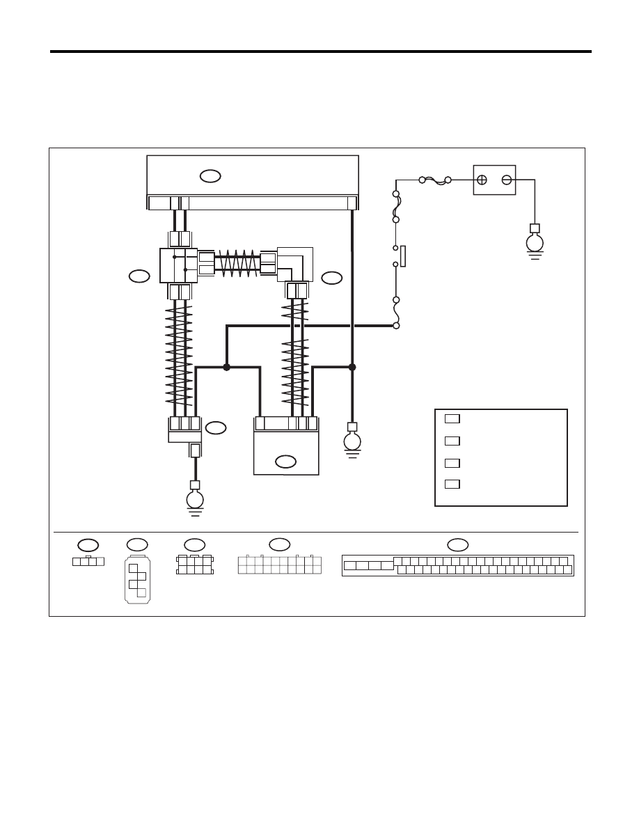
WIRING DIAGRAM:
VDC00473
1 2 3 4
B310
VDCCM & H/U
25
10
35
B231
B230
2
4
1
1
4
2
3
3
STEERING
ANGLE
SENSOR
YAW RATE &
LATERAL G
SENSOR
E
E
B231
SBF-6
MAIN SBF
No.33
E
IGNITION
SWITCH
BATTERY
B310
4 5 6 7 8 9
26 27 28 29 30
2 3
1
31 32 33 34 35 36
10 11
14 15 16 17 18 19
37 38 39 40
12 13
41 42 43 44 45 46
20 21
23
24
22
25
B230
1
2
3
4
TWISTED PAIR LINE
TWISTED PAIR LINE
B365
B170
CAN
JOINT
CONNECTOR
4
*
3
*
4
3
*
*
2
1 :
:
*
*
CAN
JOINT
CONNECTOR
TERMINAL No. OPTIONAL
ARRANGEMENT AMONG
1, 2, 3,11,12 AND 13
TERMINAL No. OPTIONAL
ARRANGEMENT AMONG
8, 9, 10, 18, 19 AND 20
4
3 :
:
*
*
TERMINAL No. OPTIONAL
ARRANGEMENT AMONG
1, 2, 5 AND 6
TERMINAL No. OPTIONAL
ARRANGEMENT AMONG
3, 4, 7 AND 8
2
1
* *
2
1
* *
2
1
*
*
TWISTED
PAIR LINE
B170
3 4
5 6
1 2
7 8
1 2 3 4 5 6 7 8 9 10
11 12 13 14 15 16 17 18 19 20
B365
VDC(diag)-98
Diagnostic Procedure with Diagnostic Trouble Code (DTC)
VEHICLE DYNAMICS CONTROL (VDC) (DIAGNOSTICS)
Step
Check
Yes
No
1
CHECK YAW RATE & LATERAL G SENSOR
INSTALLATION.
Is the yaw rate & lateral G sen-
sor installation bolt tightened to
7.5 N·m (0.76 kgf-m, 5.5 ft-lb)?
Go to step 2.
Tighten the yaw
rate & lateral G
sensor installation
bolt.
2
CHECK LATERAL G SENSOR OUTPUT.
1) Park the vehicle on a level surface.
2) Select {Current Data Display & Save} in the
Subaru Select Monitor.
3) Read the lateral G sensor output displayed
on screen.
Is the indicated reading on the
monitor display –1.5 — 1.5 m/s
2
?
Go to step 3.
Replace the yaw
rate & lateral G
sensor.
3
CHECK LATERAL G SENSOR OUTPUT.
1) Turn the ignition switch to OFF.
2) Remove the yaw rate & lateral G sensors
from vehicle.
3) Turn the ignition switch to ON, and select the
{Current Data Display & Save} in Subaru Select
Monitor.
4) Read the lateral G sensor output displayed
on screen.
When the yaw rate & lateral G
sensor is inclined 90° to the
right, is the indicated value 6.8 —
12.8 m/s
2
?
Go to step 4.
Replace the yaw
rate & lateral G
sensor.
4
CHECK LATERAL G SENSOR.
Read the lateral G sensor output displayed on
screen.
When the yaw rate & lateral G
sensor is inclined 90° to the left,
is the indicated value –6.8 —
–12.8 m/s
2
?
Go to step 5.
Replace the yaw
rate & lateral G
sensor.
5
CHECK POOR CONTACT IN CONNECTORS.
Turn the ignition switch to OFF.
Is there poor contact in connec-
tor between VDCCM& H/U and
yaw rate & lateral G sensor?
Repair the connec-
tor.
Go to step 6.
6
CHECK VDCCM&H/U.
1) Connect all connectors.
2) Clear the memory. <Ref. to VDC(diag)-23,
Clear Memory Mode.>
3) Perform the Inspection Mode. <Ref. to
VDC(diag)-22, Inspection Mode.>
4) Read the DTC.
Is the same DTC displayed?
Replace the
VDCCM only.
<Ref. to VDC-10,
REPLACEMENT,
VDC Control Mod-
ule and Hydraulic
Control Unit
(VDCCM&H/U).>
Go to step 7.
7
CHECK OTHER DTC DETECTION.
Is any other DTC displayed?
Perform the diag-
nosis according to
DTC. <Ref. to
VDC(diag)-34, List
of Diagnostic Trou-
ble Code (DTC).>
Temporary poor
contact occurs.
Нет комментариевНе стесняйтесь поделиться с нами вашим ценным мнением.
Текст