Subaru Legacy IV (2008 year). Service manual — part 943
VDC(diag)-87
Diagnostic Procedure with Diagnostic Trouble Code (DTC)
VEHICLE DYNAMICS CONTROL (VDC) (DIAGNOSTICS)
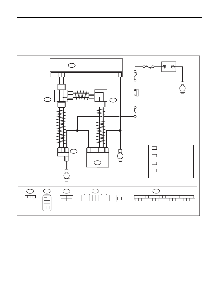
AR:DTC C0072 VOLTAGE INPUTTED TO YAW RATE SENSOR EXCEEDS
SPECIFICATION
DTC DETECTING CONDITION:
Defective yaw rate sensor
TROUBLE SYMPTOM:
VDC does not operate.
WIRING DIAGRAM:
VDC00473
1 2 3 4
B310
VDCCM & H/U
25
10
35
B231
B230
2
4
1
1
4
2
3
3
STEERING
ANGLE
SENSOR
YAW RATE &
LATERAL G
SENSOR
E
E
B231
SBF-6
MAIN SBF
No.33
E
IGNITION
SWITCH
BATTERY
B310
4 5 6 7 8 9
26 27 28 29 30
2 3
1
31 32 33 34 35 36
10 11
14 15 16 17 18 19
37 38 39 40
12 13
41 42 43 44 45 46
20 21
23
24
22
25
B230
1
2
3
4
TWISTED PAIR LINE
TWISTED PAIR LINE
B365
B170
CAN
JOINT
CONNECTOR
4
*
3
*
4
3
*
*
2
1 :
:
*
*
CAN
JOINT
CONNECTOR
TERMINAL No. OPTIONAL
ARRANGEMENT AMONG
1, 2, 3,11,12 AND 13
TERMINAL No. OPTIONAL
ARRANGEMENT AMONG
8, 9, 10, 18, 19 AND 20
4
3 :
:
*
*
TERMINAL No. OPTIONAL
ARRANGEMENT AMONG
1, 2, 5 AND 6
TERMINAL No. OPTIONAL
ARRANGEMENT AMONG
3, 4, 7 AND 8
2
1
* *
2
1
* *
2
1
*
*
TWISTED
PAIR LINE
B170
3 4
5 6
1 2
7 8
1 2 3 4 5 6 7 8 9 10
11 12 13 14 15 16 17 18 19 20
B365

VDC(diag)-88
Diagnostic Procedure with Diagnostic Trouble Code (DTC)
VEHICLE DYNAMICS CONTROL (VDC) (DIAGNOSTICS)
Step
Check
Yes
No
1
CHECK YAW RATE & LATERAL G SENSOR
POWER SUPPLY.
1) Turn the ignition switch to OFF.
2) Disconnect the connector from yaw rate &
lateral G sensor.
3) Turn the ignition switch to ON.
4) Measure the voltage between yaw rate &
lateral G sensor and chassis ground.
Connector & terminal
(B230) No. 1 (+) — Chassis ground (–):
Is the voltage 10 — 15 V?
Go to step 2.
Repair the power
supply circuit of the
yaw rate & lateral
G sensor.
2
CHECK YAW RATE & LATERAL G SENSOR
GROUND CIRCUIT.
Measure the resistance between the yaw rate &
lateral G sensor and chassis ground.
Connector & terminal
(B230) No. 4 — Chassis ground:
Is the resistance less than 0.5
:? Go to step 3.
Repair the ground
circuit of the yaw
rate & lateral G
sensor.
3
CHECK YAW RATE & LATERAL G SENSOR.
1) Turn the ignition switch to OFF.
2) Connect all connectors.
3) Clear the memory. <Ref. to VDC(diag)-23,
Clear Memory Mode.>
4) Perform the Inspection Mode. <Ref. to
VDC(diag)-22, Inspection Mode.>
5) Read the DTC.
Is the same DTC displayed?
Replace the yaw
rate & lateral G
sensor.
Go to step 4.
4
CHECK OTHER DTC DETECTION.
Is any other DTC displayed?
Perform the diag-
nosis according to
DTC. <Ref. to
VDC(diag)-34, List
of Diagnostic Trou-
ble Code (DTC).>
Temporary poor
contact occurs.
VDC(diag)-89
Diagnostic Procedure with Diagnostic Trouble Code (DTC)
VEHICLE DYNAMICS CONTROL (VDC) (DIAGNOSTICS)
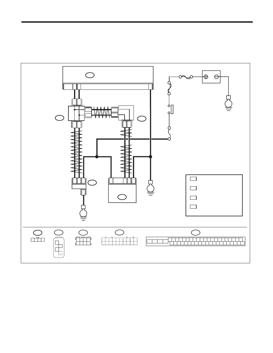
AS:DTC C0072 ABNORMAL YAW RATE SENSOR REFERENCE VOLTAGE
DTC DETECTING CONDITION:
Defective yaw rate sensor
TROUBLE SYMPTOM:
VDC does not operate.
WIRING DIAGRAM:
VDC00473
1 2 3 4
B310
VDCCM & H/U
25
10
35
B231
B230
2
4
1
1
4
2
3
3
STEERING
ANGLE
SENSOR
YAW RATE &
LATERAL G
SENSOR
E
E
B231
SBF-6
MAIN SBF
No.33
E
IGNITION
SWITCH
BATTERY
B310
4 5 6 7 8 9
26 27 28 29 30
2 3
1
31 32 33 34 35 36
10 11
14 15 16 17 18 19
37 38 39 40
12 13
41 42 43 44 45 46
20 21
23
24
22
25
B230
1
2
3
4
TWISTED PAIR LINE
TWISTED PAIR LINE
B365
B170
CAN
JOINT
CONNECTOR
4
*
3
*
4
3
*
*
2
1 :
:
*
*
CAN
JOINT
CONNECTOR
TERMINAL No. OPTIONAL
ARRANGEMENT AMONG
1, 2, 3,11,12 AND 13
TERMINAL No. OPTIONAL
ARRANGEMENT AMONG
8, 9, 10, 18, 19 AND 20
4
3 :
:
*
*
TERMINAL No. OPTIONAL
ARRANGEMENT AMONG
1, 2, 5 AND 6
TERMINAL No. OPTIONAL
ARRANGEMENT AMONG
3, 4, 7 AND 8
2
1
* *
2
1
* *
2
1
*
*
TWISTED
PAIR LINE
B170
3 4
5 6
1 2
7 8
1 2 3 4 5 6 7 8 9 10
11 12 13 14 15 16 17 18 19 20
B365

VDC(diag)-90
Diagnostic Procedure with Diagnostic Trouble Code (DTC)
VEHICLE DYNAMICS CONTROL (VDC) (DIAGNOSTICS)
Step
Check
Yes
No
1
CHECK POWER SUPPLY FOR YAW RATE &
LATERAL G SENSOR.
1) Turn the ignition switch to OFF.
2) Disconnect the connector from yaw rate &
lateral G sensor.
3) Turn the ignition switch to ON.
4) Measure the voltage between yaw rate &
lateral G sensor and chassis ground.
Connector & terminal
(B230) No. 1 (+) — Chassis ground (–):
Is the voltage 10 — 15 V?
Go to step 2.
Repair the power
supply circuit of the
yaw rate & lateral
G sensor.
2
CHECK YAW RATE & LATERAL G SENSOR
GROUND CIRCUIT.
Measure the resistance between the yaw rate &
lateral G sensor and chassis ground.
Connector & terminal
(B230) No. 4 — Chassis ground:
Is the resistance less than 0.5
:? Go to step 3.
Repair the ground
circuit of the yaw
rate & lateral G
sensor.
3
CHECK VDCCM&H/U.
1) Turn the ignition switch to OFF.
2) Connect all connectors.
3) Clear the memory. <Ref. to VDC(diag)-23,
Clear Memory Mode.>
4) Perform the Inspection Mode. <Ref. to
VDC(diag)-22, Inspection Mode.>
5) Read the DTC.
Is the same DTC displayed?
Replace the yaw
rate & lateral G
sensor.
Go to step 4.
4
CHECK OTHER DTC DETECTION.
Is any other DTC displayed?
Perform the diag-
nosis according to
DTC. <Ref. to
VDC(diag)-34, List
of Diagnostic Trou-
ble Code (DTC).>
Temporary poor
contact occurs.
Нет комментариевНе стесняйтесь поделиться с нами вашим ценным мнением.
Текст